Air conditioner indoor unit

A technology for air-conditioning indoor units and casings, applied in air-conditioning systems, space heating and ventilation, heating methods, etc., can solve the problems of large wind speed and pressure loss, increased noise, and limited adjustment range, and achieve increased air supply The effect of increasing the angle, increasing the angle range, and expanding the air supply range

Active Publication Date: 2017-09-15
QINGDAO HAIER AIR CONDITIONER GENERAL CORP LTD +2
View PDF7 Cites 0 Cited by
  • Summary
  • Abstract
  • Description
  • Claims
  • Application Information

AI Technical Summary

Problems solved by technology

However, the guide plate is exposed outside the casing of the air-conditioning indoor unit, which seriously affects the overall appearance of the air-conditioning indoor unit, and the mechanical noise brought by the stepping motor used to drive the guide plate to swing and the noise generated by itself when the guide plate swings are very Big
At the same time, the adjustment range of the method of adjusting the air outlet direction through the guide plate is limited, and it is difficult to meet the air supply requirements in a wide range
Even on the basis of traditional wall-mounted air-conditioning indoor units, some unconventional means are used to make the fluid rise or blow sideways, the loss of wind speed and wind pressure is relatively large, resulting in high power consumption of air-conditioning indoor units and further increase in noise

Method used


Image

  • Air conditioner indoor unit
  • Air conditioner indoor unit
  • Air conditioner indoor unit

Examples


Embodiment Construction

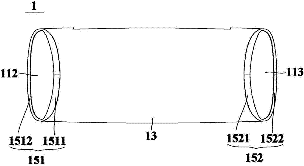
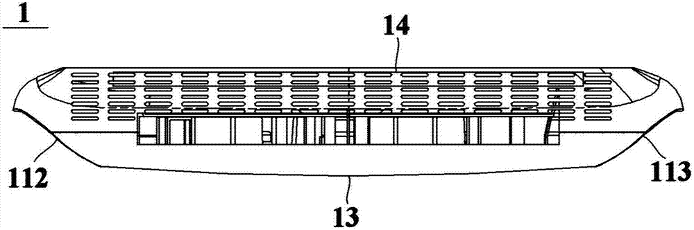
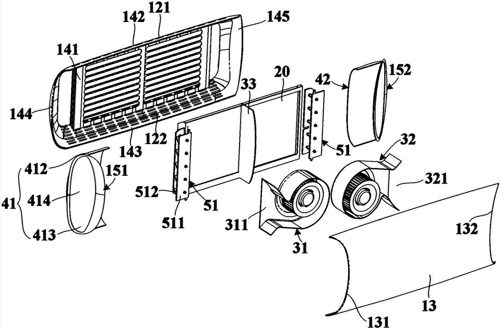
[0047] An embodiment of the present invention provides an air conditioner indoor unit, figure 1 is a schematic front view of an air conditioner indoor unit according to an embodiment of the present invention, figure 2 is a schematic top view of an air conditioner indoor unit according to an embodiment of the present invention, image 3 is a schematic exploded view of an air conditioner indoor unit according to an embodiment of the present invention, Figure 4 is a schematic sectional view of an air conditioner indoor unit according to an embodiment of the present invention. see Figure 1 to Figure 4 , the air conditioner indoor unit 1 of the embodiment of the present invention includes a casing, a heat exchange device 20 , a first fan 31 , a second fan 32 , a first air guide channel 61 and a second air guide channel 62 .

[0048]The casing has at least one air inlet, and a first side air outlet 112 and a second side air outlet 113 respectively located on two sides of the c...


PUM


Abstract

The invention relates to an air conditioner indoor unit which comprises a unit shell, a heat exchange device, a first draught fan, a second draught fan, a first air guide channel and a second air guide channel. The unit shell is provided with at least one air inlet, a first lateral air outlet and a second lateral air outlet, wherein the first lateral air outlet and the second lateral air outlet are located in the two sides of the unit shell correspondingly and face the lateral front sides of the unit shell. The heat exchange device is arranged in the unit shell and is configured to conduct heat exchange with air flowing through the heat exchange device. The first draught fan and the second draught fan are arranged in a flowing path between the heat exchange device and the first lateral air outlet and a flowing path between the heat exchange device and the second lateral air outlet correspondingly so that air obtained after heat exchange of the heat exchange device can be promoted to flow towards the first lateral air outlet and the second lateral air outlet correspondingly. The first air guide channel communicates with the first draught fan and the first lateral air outlet, and the second air guide channel communicates with the second draught fan and the second lateral air outlet. At least one air guide channel in the first air guide channel and the second air guide channel is internally provided with a movable air guide mechanism. Thus, the air supply range of the air conditioner indoor unit is enlarged, and noise of the air conditioner indoor unit during running is lowered.

Description

technical field [0001] The invention relates to air-conditioning technology, in particular to an air-conditioning indoor unit. Background technique [0002] At present, the traditional wall-mounted air conditioner indoor unit mostly uses downward air outlet, which will cause cold or hot air to blow directly to the human body, which is not conducive to user comfort experience and physical health. The air outlet of the air conditioner indoor unit is usually provided with a guide plate to adjust the air outlet direction of the air outlet by swinging the guide plate up and down or left and right. However, the guide plate is exposed outside the casing of the air-conditioning indoor unit, which seriously affects the overall appearance of the air-conditioning indoor unit, and the mechanical noise brought by the stepping motor used to drive the guide plate to swing and the noise generated by itself when the guide plate swings are very big. At the same time, the adjustment range of...

Claims


Application Information

Patent Timeline
Patent Type & Authority Applications(China)
IPC IPC(8): F24F1/00F24F13/10F24F13/24
CPCF24F1/0007F24F13/10F24F13/24
Inventor 李健王永涛关婷婷闫宝升
Owner QINGDAO HAIER AIR CONDITIONER GENERAL CORP LTD
Why Eureka
Try Eureka