Rotating direct-driven electric diaphragm

A direct-drive, aperture technology, applied in optics, optical components, instruments, etc., can solve problems such as high production costs and poor adjustment stability, and achieve the effects of reducing driving resistance, avoiding stuttering, and stabilizing lighting conditions

Pending Publication Date: 2017-09-15
XI'AN INST OF OPTICS & FINE MECHANICS - CHINESE ACAD OF SCI
View PDF7 Cites 5 Cited by
  • Summary
  • Abstract
  • Description
  • Claims
  • Application Information

AI Technical Summary

Problems solved by technology

[0005] The purpose of the present invention is to provide a rotary direct-drive electric diaphragm, which eliminates the intermediate transmission link and solves the technical problems of high production cost and poor adjustment stability of the existing electric adjustable diaphragm

Method used


Image

  • Rotating direct-driven electric diaphragm
  • Rotating direct-driven electric diaphragm
  • Rotating direct-driven electric diaphragm

Examples


Embodiment 1

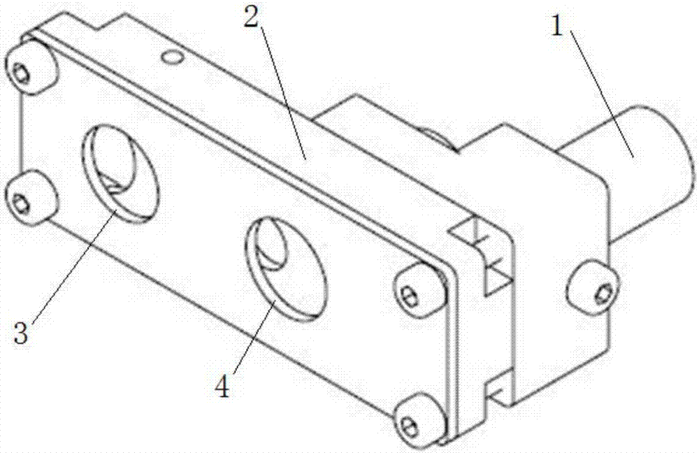
[0030] Such as figure 1 As shown, this embodiment is a rotary direct-drive electric diaphragm, which includes a motor 1 and a diaphragm main body 2 with a rectangular inner cavity.

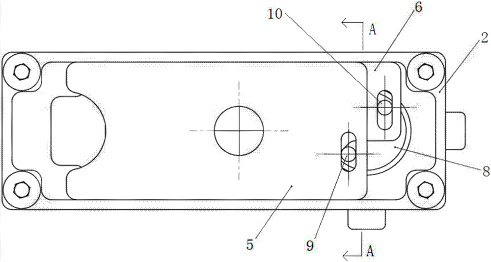
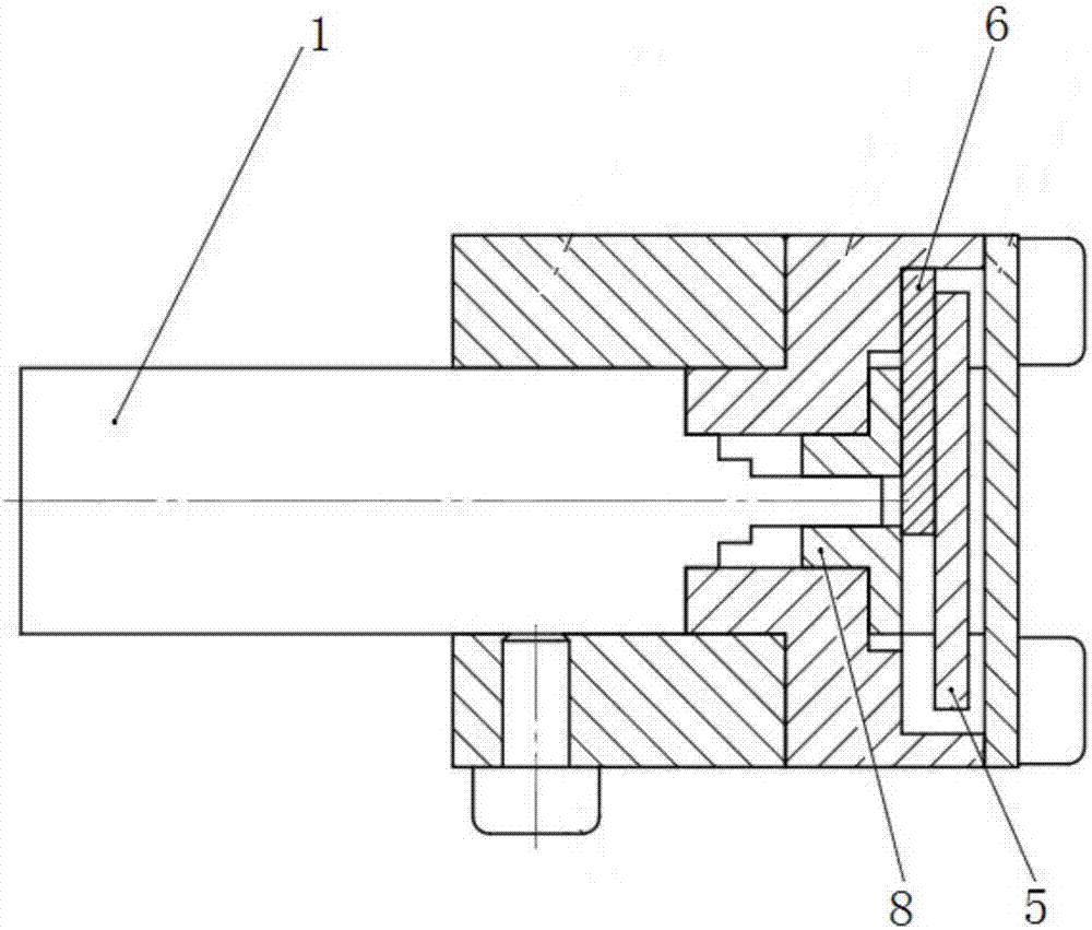
[0031] see Figure 2 to Figure 5 A rectangular first baffle 5 and a rectangular second baffle 6 are provided in the inner cavity of the diaphragm main body 2 , and the second baffle 6 is provided with a diaphragm hole 7 . The motor 1 is connected with the rotor 8, and the rotor 8 is provided with two first sliders 9 and a second slider 10 in eccentric positions, and the first baffle 5 and the second baffle 6 are respectively provided with two sliders. Compatible sliding grooves. Wherein, the two sliders are sliders with a cylindrical protrusion structure, and the sliding groove is a sliding groove with a waist-shaped hole structure. The motor 1 drives the rotor 8 to rotate, and the slider on the rotor 8 slides in the sliding groove, thereby driving the first baffle 5 and the second baffle 6 to ...

Embodiment 2

[0033] Such as Image 6 As shown, this embodiment is another rotary direct-drive electric diaphragm, which includes a motor 1 and a diaphragm main body 2 with a fan-shaped internal cavity, and the diaphragm main body 2 is provided with a light-through hole 3 and an illumination hole 4 .

[0034] see Figure 7 to Figure 10 , the inner cavity of the diaphragm main body 2 is provided with an adjusting baffle 12, and the two opposite sides of the adjusting baffle 12 are arc-shaped sides that are in sliding contact with the inner cavity of the fan-shaped structure. The motor 1 is connected with the rotor 8 , the rotor 8 is provided with a slider 13 at an eccentric position, and the adjusting baffle 12 is provided with a sliding groove matching the slider 13 . Wherein, the slider is a slider with a cylindrical protrusion structure, and the sliding groove is a sliding groove with a waist-shaped hole structure. The motor 1 drives the rotor 8 to rotate, and the slider on the rotor 8...


PUM


Abstract

The invention belongs to the technical field of optical path adjusting in the optical system, and particularly relates to a rotating direct-driven electric diaphragm. The electric diaphragm comprises a motor and a diaphragm body having an internal cavity. The diaphragm body is provided with a light through hole. The electric diaphragm is characterized in that the internal cavity of the diaphragm body is provided with an adjusting baffle plate and a rotor which is connected with the motor. The rotor is provided with a slide block arranged at the eccentric position. The adjusting baffle plate is provided with a slide groove adaptive to the slide block. The motor is adopted to drive the rotor, and the eccentric slide block on the rotor is arranged in the slide groove of the adjusting baffle plate so that the slide block slides in the slide groove when the rotor rotates, the adjusting baffle plate is driven to move in the internal cavity of the diaphragm body and opening / closing control of the light through hole can be completed. The opening / closing process of the diaphragm is directly driven by the motor so that the complex transmission structure can be eliminated, the production and processing cost of the electric diaphragm can be reduced and the adjusting stability of the diaphragm can be enhanced.

Description

technical field [0001] The invention belongs to the technical field of optical path adjustment in optical systems, and in particular relates to a rotary direct-drive electric diaphragm. Background technique [0002] The aperture can control the on-off of the optical path during the optical path debugging and working process of the optical system, and the opening and closing of the aperture can be controlled in two ways: manual control and electric control. Because manual control cannot accurately grasp the opening and closing time and speed of the aperture, and in some special application scenarios (such as high-power laser light path), manual control is more dangerous and the positioning accuracy is not high, so most of them need to use electric control aperture. [0003] The Chinese utility model patent CN203164511U published on August 28, 2013 proposes an electric adjustable aperture, which uses a motor to drive a screw to rotate, and then converts the rotary motion of th...

Claims


Application Information

Patent Timeline
Patent Type & Authority Applications(China)
IPC IPC(8): G02B26/02
CPCG02B26/02
Inventor 齐文博李奇张敏闫亚东何俊华韦明智薛艳博
Owner XI'AN INST OF OPTICS & FINE MECHANICS - CHINESE ACAD OF SCI
Why Eureka
Try Eureka