
Video denoising method and apparatus

A video noise reduction and noise reduction technology, which is applied in the direction of TV, color TV, color TV parts, etc., can solve the problems of staying in the scientific research stage, high algorithm complexity, unnatural images, etc., and achieve the effect of protection and noise reduction. The effect of precise search area and faster matching speed

Active Publication Date: 2017-09-15
北京飞识科技有限公司
View PDF7 Cites 10 Cited by
  • Summary
  • Abstract
  • Description
  • Claims
  • Application Information

AI Technical Summary

Problems solved by technology

[0005] However, as the current better noise reduction algorithm, BM3D has a shortcoming that the algorithm often has the phenomenon of "filtering", that is, the image (especially at the edge) is not clear because the noise is filtered too "clean". nature
In addition, the reason why BM3D is not widely used is that the algorithm is extremely complex, so it only stays in the scientific research stage

Method used


Image

  • Video denoising method and apparatus
  • Video denoising method and apparatus
  • Video denoising method and apparatus

Examples


Embodiment 1

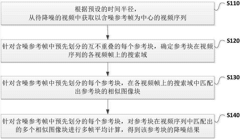
[0059] refer to figure 1 , which shows an exemplary flowchart of a video noise reduction method according to an embodiment of the present application.

[0060] like figure 1 As shown, the video noise reduction method of an embodiment of the present application may include the following steps:

[0061] S110: Acquire a video sequence centered on a noisy reference frame from the video to be denoised according to a preset time radius.

[0062] In this application scheme, the video to be denoised can be expressed as:

[0063] z(x,t)=y(x,t)+n(x,t), x∈X,t∈T (Formula 1)

[0064] Among them, y(x,t), n(x,t), z(x,t) respectively represent the original image, noise image and noisy image of the video at time t, and x represents the pixel position on a certain frame of image , X represents the set of pixel positions in the frame, and T represents the set of all moments in the video.

[0065] Suppose the video plays to t i The image to be denoised at a certain frame at a time is the no...

Embodiment 2

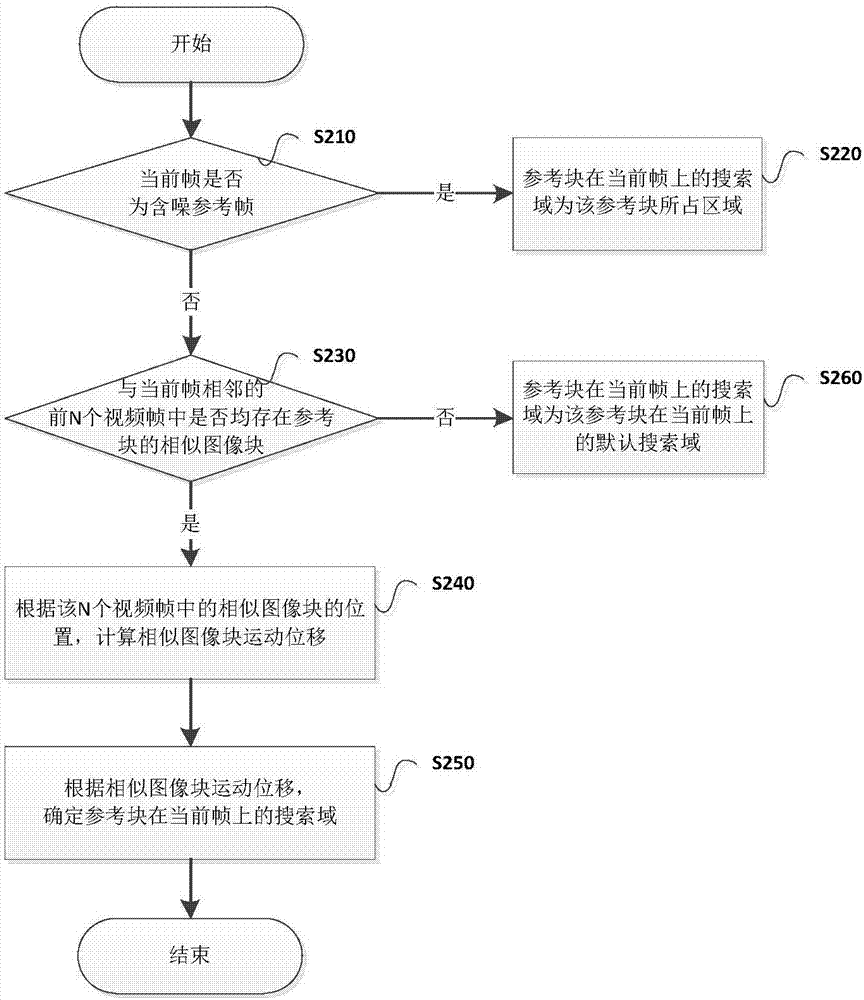
[0107] The inventors of the present invention found that the block matching process in the BM3D algorithm is the most time-consuming part, and when the traversal of a large search domain is completed, there are often many invalid calculations, which greatly affects the speed of the algorithm. Therefore, the present invention combines the idea of ​​motion estimation to accurately locate the search domain to increase the speed of similar block matching between frames. The core of the speed-up is to predict the two parameters of the center position of the search domain and the radius of the search domain, that is, to reduce the scope of the search domain, save unnecessary block-to-block calculations, and reduce the amount of calculations.

[0108] In the second embodiment of the present application, based on the video noise reduction scheme combined with the "non-local" noise reduction method and the "multi-frame average" noise reduction method provided in the first embodiment, it...


PUM


Abstract

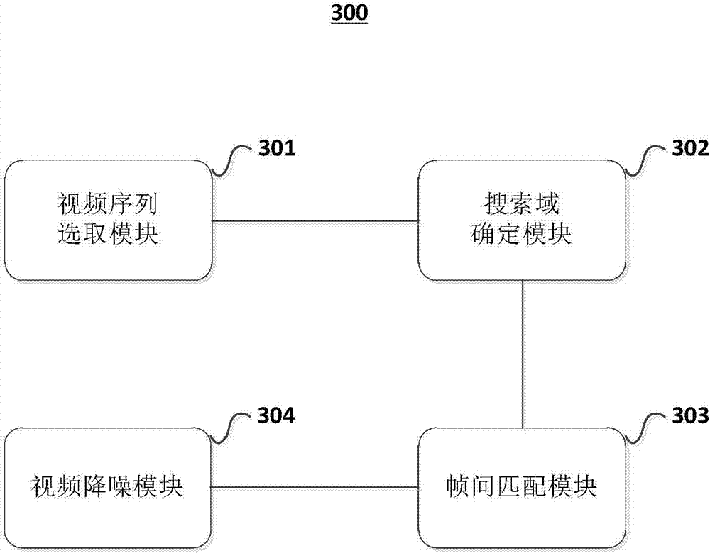
The invention discloses a video denoising method and apparatus. The method comprises the following steps: obtaining a video sequence using a noise-containing reference frame as the center from a to-be-denoised video according to a preset time radius; executing the following denoising operations on each reference block, which is pre-divided and is not overlapped with each other in the noise-containing reference frame: determining a search domain of the reference block on each video frame of the video sequence; matching a similar image block of the reference block in the search domain on each video frame; and performing multi-frame average calculation on the similar image blocks of a plurality of reference blocks matched by the reference block in the video sequence frames to obtain a denoising result of the reference block. By application of the scheme provided by the invention, the algorithm complexity can be reduced, the denoising efficiency can be improved, and meanwhile, the denoising effect of noise inhibition and edge protection can be basically guaranteed.

Description

technical field [0001] The present disclosure generally relates to the technical field of digital video image processing, and specifically relates to a video noise reduction method and device. Background technique [0002] Images are an important source of information. About 70% of the information that humans obtain comes from vision, so video and images have become the main means for people to disseminate information. However, the video is often disturbed by noise during the generation and transmission process, which affects the visual effect and conceals a large amount of useful information, which adversely affects the subsequent processing such as segmentation, detection, and recognition. Therefore, in order to highlight more useful information, it is necessary to perform noise reduction preprocessing on the video. [0003] Noise reduction preprocessing has long been the focus and difficulty of research by scholars at home and abroad. Researchers from various countries c...

Claims


Application Information

Patent Timeline
Patent Type & Authority Applications(China)
IPC IPC(8): H04N5/21H04N5/14
CPCH04N5/145H04N5/21
Inventor 刘长松姚正斌陈会娟
Owner 北京飞识科技有限公司
Learn More