Novel LED control drive circuit

A driving circuit and LED lighting technology, applied in electric light sources, electrical components, electroluminescent light sources, etc., can solve the problems of high capacitance withstand voltage, high cost, large LED lamp ripple, etc., and reduce the LED output voltage ripple. Wave, life guarantee, cost reduction effect

Active Publication Date: 2017-09-15
无锡恒芯微科技有限公司
View PDF5 Cites 1 Cited by
  • Summary
  • Abstract
  • Description
  • Claims
  • Application Information

AI Technical Summary

Problems solved by technology

Most of the LED drive circuits on the market use BCM and DCM modes. Such a structure has large ripples for LED lights, and filter capacitors need to be connected at both ends of the LED. Especially for non-isolated systems, due to the relatively high output voltage, it is necessary to The capacitance withstand voltage is relatively high, and the cost is relatively high

Method used


Image

  • Novel LED control drive circuit
  • Novel LED control drive circuit
  • Novel LED control drive circuit

Examples


Embodiment Construction

[0018] The specific implementation manners of the present invention will be described in detail below in conjunction with the accompanying drawings.

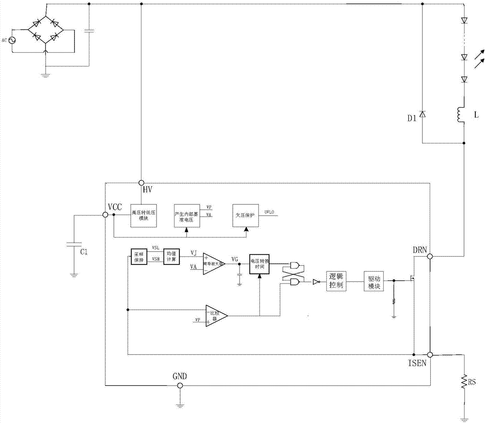
[0019] Such as figure 1 As shown, a novel LED control drive circuit of the present invention includes a power supply module, an LED lighting circuit, and an LED dimming circuit. The LED lighting circuit includes a light emitting diode, an inductor, and a Schottky tube. When the lamp discharges, this discharge time is the demagnetization time; otherwise, it is the magnetization time.

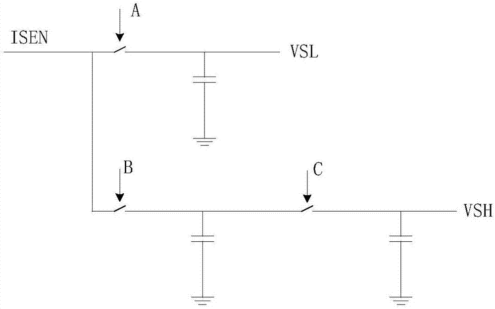
[0020] The LED dimming circuit includes a high-voltage to low-voltage module, an internal reference voltage generation module, an undervoltage protection module, a sampling module, an average value calculation module, a transconductance amplifier, a comparator, a voltage conversion time module, and a MOFET for controlling the on-off of the LED lighting circuit. Tube and MOFET tube drive module.

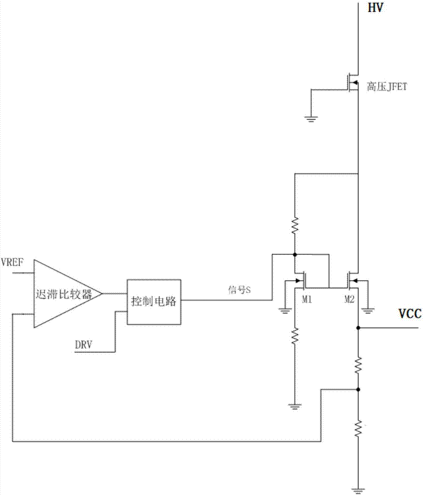
[0021] The principle of the high-voltage to low-vo...


PUM


Abstract

The invention provides a novel LED control drive circuit and relates to the technical field of LED drive. The circuit mainly comprises a power supply module, an LED lighting circuit and an LED dimming circuit. The LED dimming circuit comprises an internal reference voltage generation module, a sampling module, a mean value calculation method, a transconductance amplifier, a comparator, a voltage conversion time module, a MOFET tube which controls on and off of the LED lighting circuit, and a MOFET tube drive module. The positive end of the comparator is connected with voltage VP, and the output end is connected with a voltage conversion time module and the MOFET tube drive module. The positive end of the transconductance amplifier is connected with voltage VJ, and the negative end is connected with voltage VA. The voltage conversion time module converts voltage VG into a pulse signal corresponding to pulse width. The MOFET tube drive module converts the pulse signal into a current signal to drive the MOFET tube. The system can enter a CCM mode to reduce the LED output voltage ripple. Both ends of an LED do not need filter capacitors. The service life of an LED lamp is well protected. An external circuit is simplified. The cost is reduced.

Description

technical field [0001] The invention relates to the technical field of LED driving, in particular to a novel LED control driving circuit. Background technique [0002] At present, LED driving technology is becoming more and more mature, and the requirements for cost are also getting higher and higher. Most of the LED drive circuits on the market use BCM and DCM modes. Such a structure has large ripples for LED lights, and filter capacitors need to be connected at both ends of the LED. Especially for non-isolated systems, due to the relatively high output voltage, it is necessary to The capacitor withstand voltage is relatively high, and the cost is relatively high. Contents of the invention [0003] The technical problem to be solved by the present invention is to solve the above-mentioned deficiencies in the prior art, and provide a control driving circuit that can reduce LED ripples and does not need to connect filter capacitors to the ends of the LEDs. [0004] In ord...

Claims


Application Information

Patent Timeline
Patent Type & Authority Applications(China)
IPC IPC(8): H05B33/08H05B44/00
CPCH05B45/00
Inventor 吴建良顾南昌吴洁
Owner 无锡恒芯微科技有限公司
Why Eureka
Try Eureka