Steel backing cleaning device for producing brake pad

A cleaning device and a technology for brake pads, applied in the field of brake pad production, can solve the problems of complex operation, low work efficiency, unclean cleaning, etc., and achieve the effect of improving the cleaning effect and increasing the cleaning area.

Inactive Publication Date: 2017-09-19
谢剑和
View PDF7 Cites 13 Cited by
  • Summary
  • Abstract
  • Description
  • Claims
  • Application Information

AI Technical Summary

Problems solved by technology

[0005] In order to overcome the shortcomings of unclean cleaning, complicated operation and low work efficiency in the prior art, the technical problem to be solved by the present invention is to provide a steel back cleaning machine for brake pad production that can be cleaned cleanly, easy to operate and high in work efficiency. device

Method used


Image

  • Steel backing cleaning device for producing brake pad
  • Steel backing cleaning device for producing brake pad
  • Steel backing cleaning device for producing brake pad

Examples


Embodiment 1

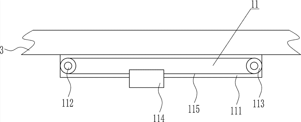
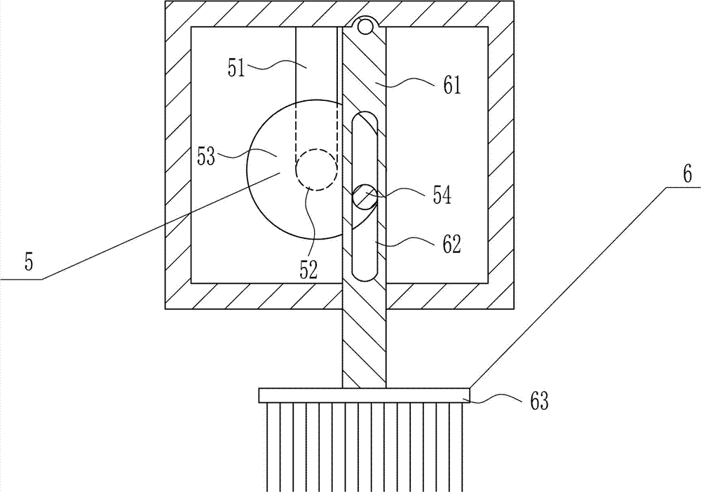
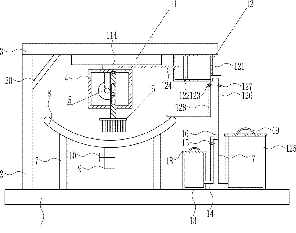
[0036] A steel back cleaning device for brake pad production, such as Figure 1-7 As shown, it includes a bottom plate 1, a bracket 2, a top plate 3, a frame body 4, a driving device 5, a cleaning device 6, outriggers 7, a cleaning frame 8, a drain pipe 9 and a drain valve 10, and the top of the bottom plate 1 is connected by bolts The bracket 2 and the support leg 7 are vertically installed, the top of the support 2 is installed horizontally with a top plate 3 connected by bolts, the cleaning frame 8 is installed on the top of the support leg 7 by a bolt connection, and the bottom of the top plate 3 is installed with a bolt connection. Frame body 4, a drive device 5 is provided on the left side of the frame body 4, a cleaning device 6 is provided on the right side of the frame body 4, and a drain pipe 9 is vertically connected to the middle of the bottom of the cleaning frame 8, and the drain pipe 9 communicates with the inside of the cleaning frame 8 , the drain pipe 9 is co...

Embodiment 2

[0038] A steel back cleaning device for brake pad production, such as Figure 1-7 As shown, it includes a bottom plate 1, a bracket 2, a top plate 3, a frame body 4, a driving device 5, a cleaning device 6, outriggers 7, a cleaning frame 8, a drain pipe 9 and a drain valve 10, and the top of the bottom plate 1 is connected by bolts The bracket 2 and the support leg 7 are vertically installed, the top of the support 2 is installed horizontally with a top plate 3 connected by bolts, the cleaning frame 8 is installed on the top of the support leg 7 by a bolt connection, and the bottom of the top plate 3 is installed with a bolt connection. Frame body 4, a drive device 5 is provided on the left side of the frame body 4, a cleaning device 6 is provided on the right side of the frame body 4, and a drain pipe 9 is vertically connected to the middle of the bottom of the cleaning frame 8, and the drain pipe 9 communicates with the inside of the cleaning frame 8 , the drain pipe 9 is co...

Embodiment 3

[0041] A steel back cleaning device for brake pad production, such as Figure 1-7 As shown, it includes a bottom plate 1, a bracket 2, a top plate 3, a frame body 4, a driving device 5, a cleaning device 6, outriggers 7, a cleaning frame 8, a drain pipe 9 and a drain valve 10, and the top of the bottom plate 1 is connected by bolts The bracket 2 and the support leg 7 are vertically installed, the top of the support 2 is installed horizontally with a top plate 3 connected by bolts, the cleaning frame 8 is installed on the top of the support leg 7 by a bolt connection, and the bottom of the top plate 3 is installed with a bolt connection. Frame body 4, a drive device 5 is provided on the left side of the frame body 4, a cleaning device 6 is provided on the right side of the frame body 4, and a drain pipe 9 is vertically connected to the middle of the bottom of the cleaning frame 8, and the drain pipe 9 communicates with the inside of the cleaning frame 8 , the drain pipe 9 is co...


PUM


Abstract

The invention belongs to the technical field of brake pad production and particularly relates to a steel backing cleaning device for producing a brake pad. The steel backing cleaning device for producing the brake pad aims at achieving the technical effects that the device is capable of conducting cleaning thoroughly, easy to operate and high in work efficiency. The steel backing cleaning device for producing the brake pad comprises a base plate, a support, a top plate, a frame body, a driving device, a cleaning device, support legs and the like. The support and the support legs are vertically mounted at the top of the base plate in a bolt-connection manner. The top plate is horizontally mounted at the top of the support in a bolt-connection manner. A cleaning frame is mounted at the tops of the support legs in a bolt-connection manner. According to the steel backing cleaning device, a hair brush moves leftwards and rightwards within a small range and a large range to clean a steel backing; the cleaning effect is good; and the steel backing cleaning device has the beneficial effects of being capable of conducting cleaning thoroughly, easy to operate and high in work efficiency.

Description

technical field [0001] The invention belongs to the technical field of brake pad production, in particular to a steel back cleaning device for brake pad production. Background technique [0002] Brake pads: generally composed of a steel back, an adhesive heat insulation layer and a friction block. The steel back needs to be painted to prevent rust. During the painting process, an SMT-4 furnace temperature tracker is used to detect the temperature distribution during the painting process to ensure quality. . The heat insulation layer is composed of materials that do not conduct heat, and the purpose is heat insulation. The friction block is composed of friction material and adhesive, which is squeezed on the brake disc or brake drum to generate friction during braking, so as to achieve the purpose of vehicle deceleration and braking. Due to friction, the friction block will be gradually worn, generally speaking, the lower the cost of the brake pads, the faster the wear. ...

Claims


Application Information

Patent Timeline
Patent Type & Authority Applications(China)
IPC IPC(8): B08B1/00B08B3/08
CPCB08B1/002B08B3/08
Inventor 周斌柯达易荣李满红
Owner 谢剑和
Why Eureka
Try Eureka