Step-type mixed gas steel cylinder

A mixed gas, step-type technology, applied in the field of gas cylinders and cylinders dedicated to mixed gases

Inactive Publication Date: 2017-09-19
镇江严彦气体有限公司
View PDF4 Cites 0 Cited by
  • Summary
  • Abstract
  • Description
  • Claims
  • Application Information

AI Technical Summary

Problems solved by technology

[0003] Aiming at the shortcomings of the existing mixed gas mixing process, the patent of the present invention provides a special steel cylinder for mixed gas

Method used


Image

  • Step-type mixed gas steel cylinder

Examples


Embodiment Construction

[0013] The principles and features of the patent of the present invention are described below in conjunction with examples, which are only used to explain the patent of the present invention, and are not used to limit the scope of the patent of the present invention.

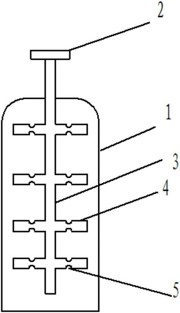
[0014] A special steel cylinder for a stepped mixed gas, comprising a gas valve 2 arranged at the top of the cylinder body at the first stage of the steel cylinder body, and a ladder-shaped long tube main branch 3 extending to the bottom of the steel cylinder body at the air inlet of the steel cylinder body, and the main branch of the long tube is The bottom end of the branch is not closed, and there is still an air outlet. The main branch of the long pipe is provided with 4 transverse branches 4 with air holes at the end. The angle between the branch 4 of the long pipe and the main branch 3 of the long pipe is 90 degrees. , the transverse branch 4 is provided with air holes 5, and the air holes 5 are mirror-symm...


PUM


Abstract

The patent of the present invention relates to a special steel cylinder for mixed gas, which is composed of a steel cylinder body and a gas valve arranged on the top of the steel cylinder body. , the bottom end of the long tube is not closed, and the upper and lower sides of the thin tube of the lateral branch part of the long tube are provided with a number of air holes. The beneficial effect of the patent of the present invention is: after gas A is input from the mouth of the gas cylinder, it is dispersed in all directions through the air holes, and then gas B is input, and gas B is also dispersed in all directions through the air holes, so as to achieve the purpose of rapid mixing and uniformity.

Description

technical field [0001] The patent of the invention relates to a gas cylinder, in particular to a steel cylinder dedicated to mixed gas, which belongs to the technical field of gas storage. Background technique [0002] At present, due to the difference in density of different gases, the newly prepared mixed gas in the steel cylinder must be shaken for at least 1 hour before the components in it can be mixed in a short time, otherwise it will take at least a week to mix naturally Evenly, it is a waste of manpower, material resources and time to mix gas like this, and the efficiency is low. Contents of the invention [0003] The patent of the present invention aims at the deficiencies in the existing mixed gas mixing process, and provides a special steel cylinder for mixed gas. [0004] The technical scheme that the patent of the present invention solves the above-mentioned technical problem is as follows: [0005] A special steel cylinder for a stepped mixed gas, comprisi...

Claims


Application Information

Patent Timeline
Patent Type & Authority Applications(China)
IPC IPC(8): F17C1/00F17C13/00
CPCF17C1/00F17C13/00F17C2265/025
Inventor 周玉洁周宏峰
Owner 镇江严彦气体有限公司
Why Eureka
Try Eureka