OPLC joint closure end protection device

A protection device and joint box technology, applied in the directions of light guides, optics, instruments, etc., to prevent relative slippage, improve torsion resistance and tensile strength, and enhance the effect of tightening force

Pending Publication Date: 2017-09-19
ZHONGTIAN TECH MARINE SYST CO LTD
View PDF3 Cites 0 Cited by
  • Summary
  • Abstract
  • Description
  • Claims
  • Application Information

AI Technical Summary

Problems solved by technology

Existing OPLC splice boxes use cables that twist or slip in the splice box

Method used


Image

  • OPLC joint closure end protection device
  • OPLC joint closure end protection device
  • OPLC joint closure end protection device

Examples


Embodiment Construction

[0019] The technical solutions of the present invention will be clearly and completely described below through specific embodiments.

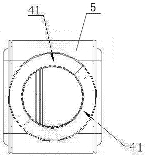
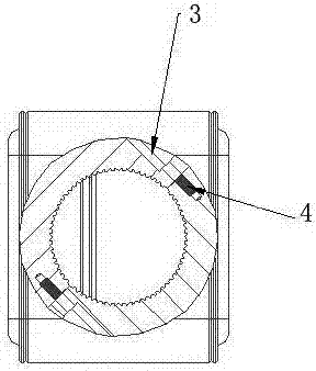
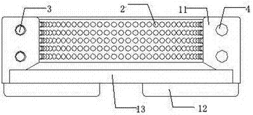
[0020] Such as Figure 1-5 As shown, it is an OPLC splice box end protection device of the present invention, the protection device is fixed on both ends of the splice box 5, and the protection device is composed of a plurality of clamping jaws 1 connected end to end through fasteners A connected ring-shaped protective sleeve with an inner hole and adjustable elasticity; the side of the jaw 1 in contact with the OPLC is provided with a special-shaped structure 2 .

[0021] Specifically, the protection device of the present invention includes 2-4 jaws 1, and the jaws 1 are engaged to form a ring-shaped protective sleeve; the end of the joint box is provided with a limiting groove and a clip for connecting with the jaws; The claw 1 includes an arc-shaped body 11 and a snap-in piece arranged on one side of the arc-shaped body 11; the snap-in piec...


PUM


Abstract

The present invention discloses an OPLC joint closure end protection device. The protection device is fixed at the two ends of a joint closure. The protection device comprises an annular protective sleeve. A plurality of clamping jaws connected end to end through fasteners to form the annular protective sleeve. The annular protective sleeve is provided with inner holes and the tightness of the annular protective sleeve is adjustable. One side of each clamping jaw, in contact with an OPLC, is provided with a special-shaped structure. The protection device disclosed by the invention effectively prevents the twisting and the sliding of a cable.

Description

technical field [0001] The invention relates to the technical field of optical fiber communication, in particular to an end protection device for an OPLC splice box. Background technique [0002] As a widely used communication technology, optical fiber communication has the incomparable advantages of other technologies such as high bandwidth, strong anti-interference ability, and excellent cost performance, and has become the first choice for communication network construction. Power FTTH adopts optical fiber composite low-voltage cable (OPLC) to realize the synchronous transmission of power flow and information flow. It is an extension of the power communication network in the power consumption link of the smart grid. An inevitable choice for social resource sharing. Existing OPLC splice boxes use cables that twist or slip in the splice box. Contents of the invention [0003] The technical problem to be solved by the present invention is to provide an OPLC splice box en...

Claims


Application Information

Patent Timeline
Patent Type & Authority Applications(China)
IPC IPC(8): G02B6/44
CPCG02B6/4446
Inventor 吴金峰郭朝阳杨华勇葛永新葛政东谢书鸿
Owner ZHONGTIAN TECH MARINE SYST CO LTD
Why Eureka
Try Eureka