Display panel and display device

A display panel and display area technology, applied in identification devices, optics, instruments, etc., can solve problems such as unfavorable narrow frame design, achieve the effect of reducing area and realizing narrow frame

Active Publication Date: 2017-09-19
XIAMEN TIANMA MICRO ELECTRONICS
View PDF6 Cites 69 Cited by
  • Summary
  • Abstract
  • Description
  • Claims
  • Application Information

AI Technical Summary

Problems solved by technology

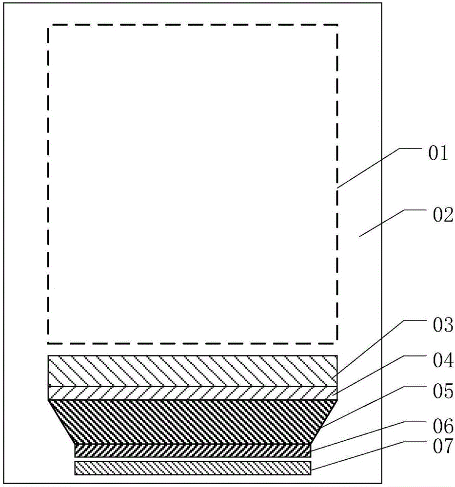
[0004] from figure 1 It can be seen that in the display panel provided by the prior art, the lower frame area contains more circuit structures, which is not conducive to the realization of a narrow frame design

Method used


Image

  • Display panel and display device
  • Display panel and display device
  • Display panel and display device

Examples


Embodiment Construction

[0032] Various exemplary embodiments of the present invention will now be described in detail with reference to the accompanying drawings. It should be noted that the relative arrangements of components and steps, numerical expressions and numerical values ​​set forth in these embodiments do not limit the scope of the present invention unless specifically stated otherwise.

[0033] The following description of at least one exemplary embodiment is merely illustrative in nature and in no way taken as limiting the invention, its application or uses.

[0034] Techniques, methods and devices known to those of ordinary skill in the relevant art may not be discussed in detail, but where appropriate, such techniques, methods and devices should be considered part of the description.

[0035] In all examples shown and discussed herein, any specific values ​​should be construed as exemplary only, and not as limitations. Therefore, other instances of the exemplary embodiment may have dif...


PUM


Abstract

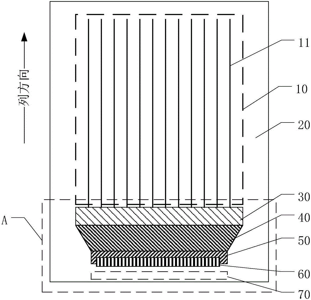
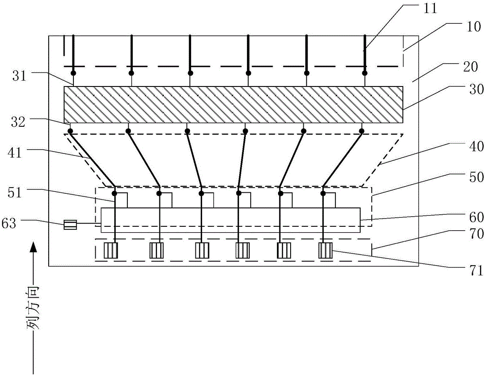
The invention discloses a display panel and a display device. The display panel comprises a display area and a non-display area; the display area comprises a plurality of parallel data lines extending in the column direction; the non-display area comprises a binding area, and a plurality of conductive bonding pads are arranged in the binding area; a multi-channel distributor, a fan-out structure, a wiring area and a test circuit are arranged between the display area and the binding area; the fan-out structure comprises a plurality of fan-out lines which extend in different directions; the wiring area comprises a plurality of wires extending in the column direction, the first ends of the wires are electrically connected with the fan-out lines, and the second ends of the wires are electrically connected with the conductive bonding pads; the output end of the test circuit is electrically connected with the wires, and the input end of the test circuit is electrically connected with the testing signal input end; in the direction perpendicular to the display panel, the wiring area and the area where the test circuit is located are overlapped. The provided display panel and the display device can reduce the area of the non-display area, and narrow bezel can be easily achieved.

Description

technical field [0001] The present invention relates to the field of display technology, and more particularly, to a display panel and a display device. Background technique [0002] With the development of display technology, display devices are required to be thinner and thinner, with narrower borders, so as to enhance user experience. [0003] figure 1 It is a schematic diagram of a display panel provided by the prior art, including a display area 01 and a non-display area 02, wherein the non-display area 02 is sequentially provided with a multiplexer circuit 03, a test circuit 04, a fan-out structure 05, and a walk-through The wiring area 06 and the binding area 07, usually, the non-display area where the demultiplexer circuit 03, the test circuit 04, the fan-out structure 05, the routing area 06, and the binding area 07 are located becomes the lower frame area. Wherein, the demultiplexer circuit 03 is used to transmit data signals to the data lines in the display pane...

Claims


Application Information

Patent Timeline
IPC IPC(8): G09F9/00G02F1/1345G02F1/1333G02F1/1362G06F3/041
CPCG02F1/13338G02F1/13452G06F3/0412G09F9/00G02F1/136254
Inventor 刘冰萍许喜爱陈国照
Owner XIAMEN TIANMA MICRO ELECTRONICS
Why Eureka
Try Eureka