Lighting control system and method with intelligent shoe

A smart shoe and lighting technology, applied in energy-saving control technology, light source, electric light source, etc., can solve problems such as inflexible design and misoperation

Inactive Publication Date: 2017-09-19
浙江大云物联科技有限公司
View PDF6 Cites 3 Cited by
  • Summary
  • Abstract
  • Description
  • Claims
  • Application Information

AI Technical Summary

Problems solved by technology

The technology disclosed above is to determine the opening and closing of the lighting device according to the position and direction of movement of the object, which is easy to cause misoperation and inflexible design

Method used


Image

  • Lighting control system and method with intelligent shoe
  • Lighting control system and method with intelligent shoe
  • Lighting control system and method with intelligent shoe

Examples


Embodiment 1

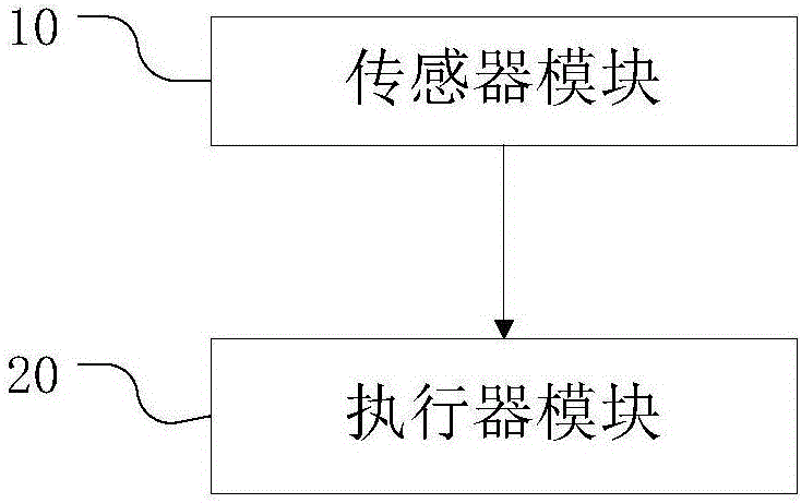
[0042] This embodiment provides a smart shoe control lighting system, such as figure 1 shown, including:

[0043] The sensor module is used to detect user action information and emit user action signals;

[0044] The actuator module is used to receive a user action signal and control to turn on the lighting device; after the lighting device is turned on, it is judged whether there is a user action signal acquired within a preset time period, and if not, it is controlled to turn off the lighting device;

[0045] The sensor module is arranged on the smart shoe or embedded in the smart shoe, and the actuator module is arranged on the circuit of the lighting device.

[0046] Among them, the sensor is a detection device, that is, a device or device that can sense the specified measured object and convert it into a usable signal according to certain rules. In this embodiment, when the user gets up at night and touches a smart shoe equipped with a sensor module, the sensor module o...

Embodiment 2

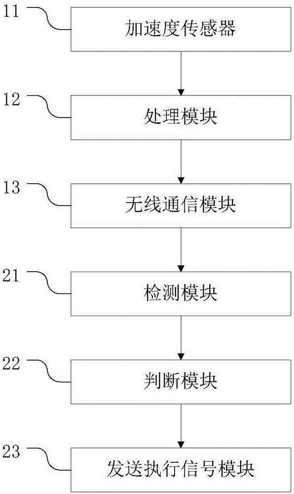
[0050] This embodiment provides another smart shoe control lighting system, such as figure 2 shown, including:

[0051] The acceleration sensor is used to generate a pulse signal when the user's movement information is detected;

[0052] A processing module, configured to receive and collect the pulse signal and convert it into a user action signal;

[0053] A wireless communication module, configured to transmit the user action signal;

[0054] The detection module is used to collect the illuminance and time of the user after receiving the user action signal, and judge whether the illuminance of the user is less than a preset value and judge whether the time of the user is within the preset time range;

[0055] In this embodiment, the acceleration sensor, the processing module and the wireless communication module all belong to the sensor module; the acceleration sensor is the component that directly receives the measurement in the sensor module and is used to output the m...

Embodiment 3

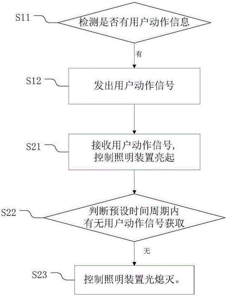
[0071] This embodiment provides a smart shoe control lighting method, such as image 3 shown, which includes the steps:

[0072] S1: Detect whether there is user action information, and if so, send a user action signal;

[0073] S2: used to receive the user action signal and control the lighting device to turn on; after the lighting device is turned on, it is judged whether there is a user action signal acquired within the preset time period, and if not, the lighting device is controlled to turn off.

[0074] Wherein step S1, detecting the action information of the user touching the smart shoe, converting the action information into an available user action signal, and emitting it. In this step, the detected action information of the user touching the smart shoes is used as an instruction to turn on the lighting device, making it more convenient for the user to turn on the lights at night.

[0075] Step S2, according to the received user action signal, automatically control ...


PUM


Abstract

The invention discloses a lighting control system and method with an intelligent shoe. The system comprises a sensor module used for detecting user action information and transmitting a user motion signal, and an actuator module used for receiving the user motion signal and controlling the switch-on of a lighting device, judging whether the user motion signal is obtained in a preset time period after the lighting device is started, and controlling the lighting device to be switched off if not. The sensor module is arranged on the intelligent shoe or embedded in the intelligent shoe. The actuator module is arranged in a circuit of the lighting device. According to the system and the method, by using the sensor module arranged on the intelligent shoe and the actuator module arranged in a circuit of the lighting device, corresponding light is on when the intelligent shoe is touched, and the light is off automatically when the intelligent shoe is still. The lighting control system is intelligent, flexible, convenient and practical.

Description

technical field [0001] The invention relates to the field of automatic lighting control systems, in particular to the field of a smart shoe control lighting system and method. Background technique [0002] Smart shoes belong to the field of smart wearable devices and have a wireless monitoring function. However, the smart shoes in the prior art only monitor and remind users or devices through wireless Bluetooth communication technology, and do not have the function of controlling devices. [0003] Automatically control the lighting system. The current automatic control lighting system includes voice-activated or light-controlled lighting system; although the voice-activated and light-controlled lighting system is more reasonable and humanized than the traditional lighting system, it has played its importance in many occasions, but this Light-like systems also have inherent drawbacks. For example, in the voice-activated lighting system, the sound will light up all the lighti...

Claims


Application Information

Patent Timeline
IPC IPC(8): H05B37/02
CPCH05B47/105H05B47/11H05B47/16H05B47/19Y02B20/40
Inventor 高云张洪仁
Owner 浙江大云物联科技有限公司
Why Eureka
Try Eureka