Moisture-proof control cabinet body and moisture-proof control cabinet

A control cabinet and controller technology, applied in the direction of cabinet/box/drawer parts, electrical equipment housing/cabinet/drawer, cooling/ventilation/heating transformation, etc., can solve the problem of control cabinet being susceptible to moisture, etc. Achieve the effect of small occupied space, reasonable design and cost saving

Pending Publication Date: 2017-09-19
GUILIN UNIVERSITY OF TECHNOLOGY
View PDF10 Cites 9 Cited by
  • Summary
  • Abstract
  • Description
  • Claims
  • Application Information

AI Technical Summary

Problems solved by technology

[0005] The purpose of the present invention is to provide a moisture-proof control cabinet, which can effectively improve the problem that the control cabinet is susceptible to moisture

Method used


Image

  • Moisture-proof control cabinet body and moisture-proof control cabinet
  • Moisture-proof control cabinet body and moisture-proof control cabinet
  • Moisture-proof control cabinet body and moisture-proof control cabinet

Examples


Embodiment 1

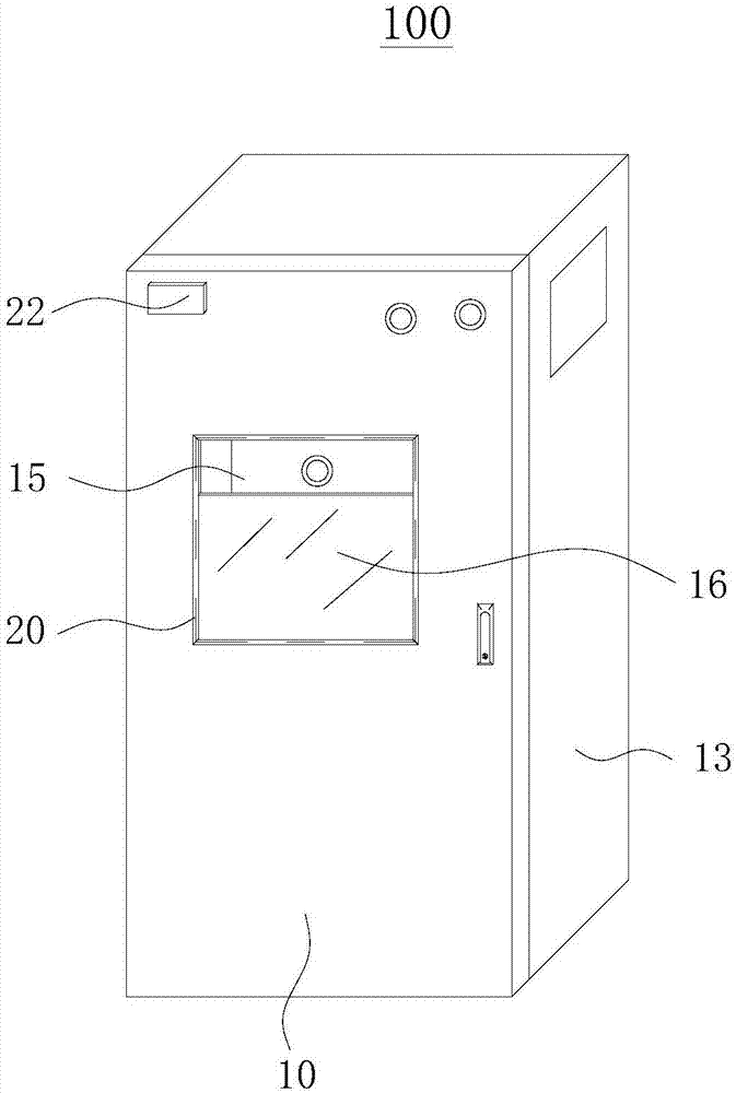
[0046] Such as figure 1 As shown, the moisture-proof control cabinet 100 provided by Embodiment 1 of the present invention includes a cabinet body, a first moisture-proof component, a second moisture-proof component and a controller.

[0047] The specific structure of each component of the moisture-proof control cabinet 100 and the corresponding relationship among them will be described in detail below.

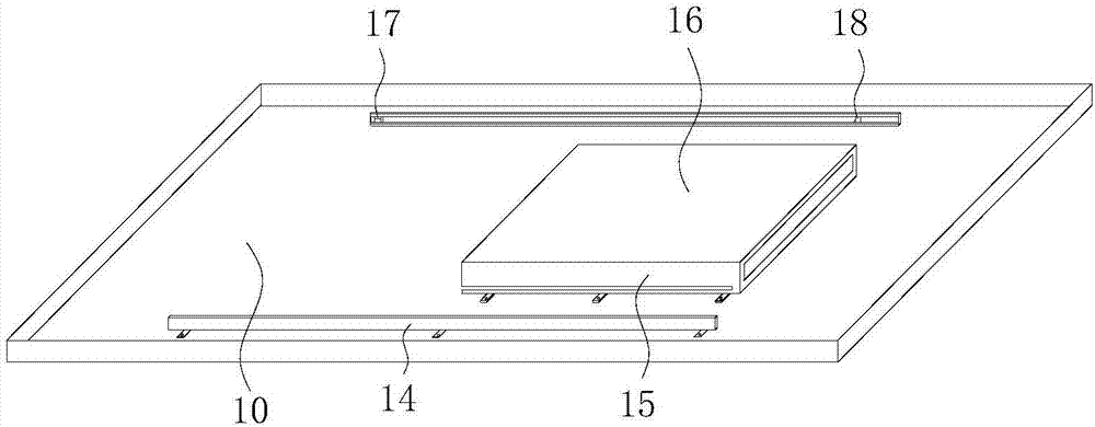
[0048] First, the specific structure of the cabinet body is introduced in detail. Please continue to refer figure 1 , the cabinet body includes a cabinet door 10, cabinet side walls 13 on both sides of the cabinet door 10, and fixing parts 15. A semicircular arc-shaped waterproof groove is arranged around the cabinet door 10 connected to the cabinet side wall 13, and the waterproof groove is embedded With sealing ring. The upper part of the cabinet door 10 is provided with a visible operation window 20. The shape of the visible operation window 20 can be various. Optionall...

Embodiment 2

[0075] Embodiment 2 of the present invention provides a moisture-proof control cabinet, including a button assembly, an electrical component assembly, and the moisture-proof control cabinet body 100 provided in Embodiment 1.

[0076] The electrical component assembly is fixedly arranged inside the moisture-proof control cabinet 100 , the electrical component assembly is connected to the wire corresponding to the button assembly, and the button assembly is fixedly arranged on the operation panel 16 .

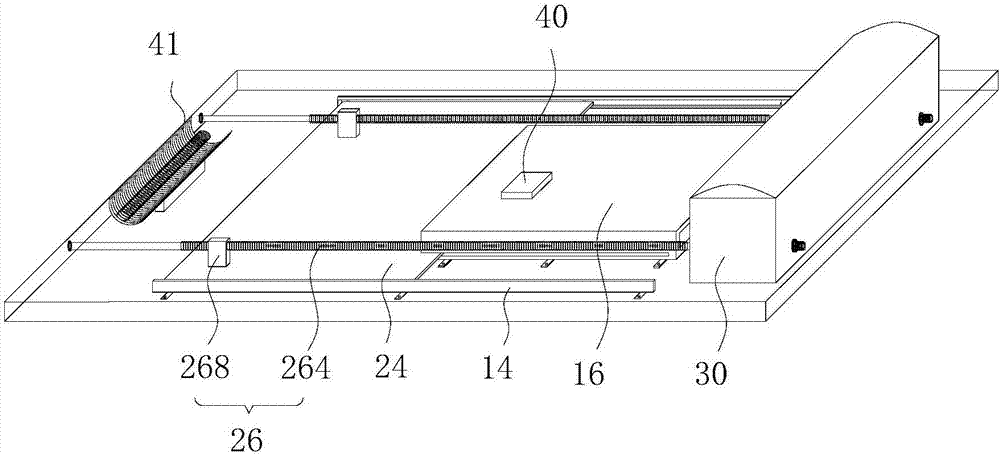
[0077] Aiming at the actual humidity outside the control cabinet and inside the cabinet, the purpose of automatic moisture-proof is achieved through the first moisture-proof component and the second moisture-proof component inside the moisture-proof control cabinet 100, and the electrical components are assembled according to the specific needs of the control cabinet during use. Not only can centralized management and operation be achieved, but also the existing control cabinets a...


PUM


Abstract

The present invention discloses a moisture-proof control cabinet body and a moisture-proof control cabinet and relates to the field of electrical equipment. The moisture-proof control cabinet body comprises a cabinet body, a first moisture-proof assembly and a second moisture-proof assembly. The cabinet body comprises a cabinet door and a fixed member. The fixed member comprises an operation panel capable of setting a button assembly. The first moisture-proof assembly comprises a first humidity sensor and a lifting closure. The first humidity sensor is arranged on the outer side of the cabinet body. The lifting closure is liftably arranged on the inner side of the cabinet door. The second moisture-proof assembly comprises a second humidity sensor and a heating member. The heating member is arranged on the cabinet body. The moisture-proof control cabinet comprises a button assembly, an electrical component assembly and a moisture-proof control cabinet body. The moisture-proof control cabinet body is reasonable in design, simple in structure, easy in maintenance and overhaul, and cost-saving, wherein the moisture-proof purpose can be realized according to actual conditions.

Description

technical field [0001] The invention relates to the field of electrical equipment, in particular to a moisture-proof control cabinet body and a moisture-proof control cabinet. Background technique [0002] With the development of science and technology, control cabinets are currently widely used in China, aiming to centralize various electrical equipment in one cabinet for management and operation. [0003] At present, the control cabinets sold on the market, when the air humidity increases, it is easy to condense water mist on the surface of the cabinet, inside the cabinet and the operation panel of the control cabinet to form water droplets, which has the defect of not being able to prevent moisture, which increases the risk of leakage and equipment burnout. There are huge security risks. [0004] To sum up, how to design a control cabinet with a moisture-proof function is a technical problem to be solved urgently by those skilled in the art. Contents of the invention ...

Claims


Application Information

Patent Timeline
IPC IPC(8): H05K5/02H05K7/20
CPCH05K5/0213H05K7/20Y02A30/14
Inventor 郑谊峰陈明霞
Owner GUILIN UNIVERSITY OF TECHNOLOGY
Why Eureka
Try Eureka