Low-energy-consumption hot ore crushing device
A crushing device and low energy consumption technology, which is applied in the field of low energy consumption hot ore crushing devices, can solve problems such as high production environment temperature, high component damage rate, and influence on fine ore processing, and achieve overall energy consumption reduction, production efficiency improvement, and cooling unstable effect
- Summary
- Abstract
- Description
- Claims
- Application Information
AI Technical Summary
Problems solved by technology
Method used
Image

Examples
Embodiment 1
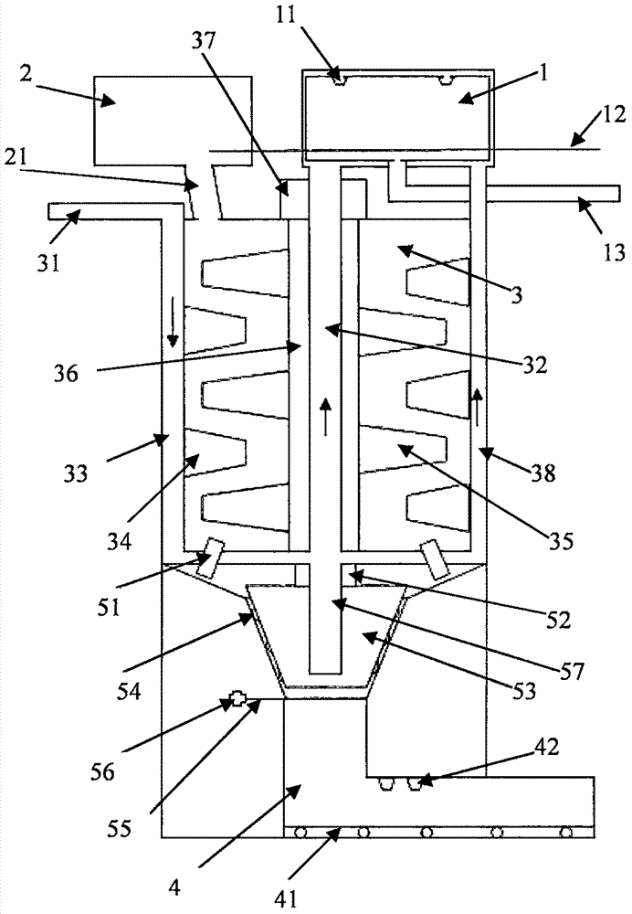
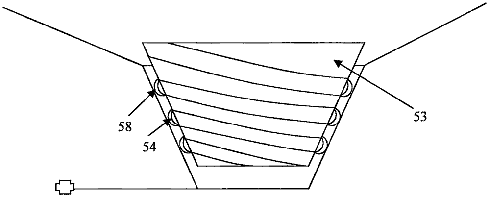
[0029] Such as figure 1 and figure 2 as shown,
[0030] A low energy consumption thermal ore crushing device includes a preparation chamber, a heating chamber, a crushing chamber, a grinding chamber and a conveying chamber.
[0031] The preparation chamber is used to preheat and moisten the raw ore. A nozzle of the preparation chamber is arranged at the top of the interior, a raw ore conveyor belt is arranged horizontally at the middle and lower part, and a circulating water outlet is arranged on the lower side of the raw ore conveyor belt. One end of the raw ore conveyor belt It is connected with the raw material inlet of the raw ore, and the other end is connected with the heating chamber, and a circulating water channel is hollowly arranged on each wall of the entire shell of the preparation chamber.
[0032] The heating chamber is used to heat the raw ore, and heating elements are arranged on the inner four walls, and the outlet of the heating chamber is connected to th...
Embodiment 2
[0049] Such as figure 1 and figure 2 Shown:
[0050] A low energy consumption thermal ore crushing device includes a preparation chamber, a heating chamber, a crushing chamber, a grinding chamber and a conveying chamber.
[0051] The preparation chamber is used to preheat and moisten the raw ore. A nozzle of the preparation chamber is arranged at the top of the interior, a raw ore conveyor belt is arranged horizontally at the middle and lower part, and a circulating water outlet is arranged on the lower side of the raw ore conveyor belt. One end of the raw ore conveyor belt It is connected with the raw material inlet of the raw ore, and the other end is connected with the heating chamber, and a circulating water channel is hollowly arranged on each wall of the entire shell of the preparation chamber.
[0052] The heating chamber is used to heat the raw ore. Heating elements are arranged on the inner four walls, and the outlet of the heating chamber is arranged in the lower ...
Embodiment 3
[0069] A low energy consumption thermal ore crushing device includes a preparation chamber, a heating chamber, a crushing chamber, a grinding chamber and a conveying chamber.
[0070] The preparation chamber is used to preheat and moisten the raw ore. A nozzle of the preparation chamber is arranged at the top of the interior, a raw ore conveyor belt is arranged horizontally in the middle and lower part, and a circulating water outlet is arranged on the lower side of the raw ore conveyor belt. One end of the raw ore conveyor belt It is connected with the raw material inlet of the raw ore, and the other end is connected with the heating chamber, and a circulating water channel is hollowly arranged on each wall of the whole shell of the preparation chamber.
[0071] The heating chamber is used to heat the raw ore, and heating elements are arranged on the inner four walls, and the outlet of the heating chamber is connected to the crushing chamber at the lower part, and the heated r...
PUM
 Abstract
Description
Claims
Application Information
 - R&D
- Intellectual Property
- Life Sciences
- Materials
- Tech Scout
- Unparalleled Data Quality
- Higher Quality Content
- 60% Fewer Hallucinations
Browse by: Latest US Patents, China's latest patents, Technical Efficacy Thesaurus, Application Domain, Technology Topic, Popular Technical Reports.
© 2025 PatSnap. All rights reserved.Legal|Privacy policy|Modern Slavery Act Transparency Statement|Sitemap|About US| Contact US: help@patsnap.com