
Hybrid coupling device based on mechanical automatic transmission

A technology of automatic transmission and coupling device, which is applied to the arrangement of multiple prime movers of power devices, pneumatic power devices, and general power devices, and can solve the problem of unbalanced technical complexity and power performance, power transmission chain, etc. Shafting torsional vibration, poor power output effect and other problems, to reduce the risk of shafting torsional vibration, reduce the size, and use the installation space

Inactive Publication Date: 2017-09-22
湖州伊立机械有限公司
View PDF5 Cites 3 Cited by
  • Summary
  • Abstract
  • Description
  • Claims
  • Application Information

AI Technical Summary

Problems solved by technology

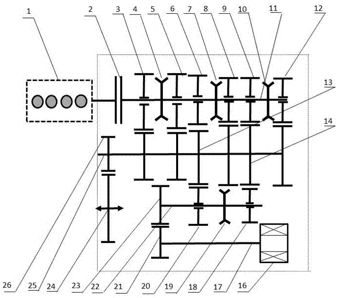
[0004] The technical purpose of the present invention is to fully consider the needs of target models (A-class cars, compact cars, B-class cars and SUVs) for hybrid systems, and based on current industrial resources, provide a hybrid system based on a mechanical automatic transmission. The coupling device solves the problem that the torque is easily interrupted during the shifting process of the existing power system, the long power transmission chain is likely to cause torsional vibration of the shafting, the installation space is limited, low-speed high-torque and high-speed cruise cannot be balanced, the impact of shifting is large, and the life of parts Shorter, poor power output effect, unable to achieve balance between technical complexity and power performance

Method used


Image

  • Hybrid coupling device based on mechanical automatic transmission
  • Hybrid coupling device based on mechanical automatic transmission
  • Hybrid coupling device based on mechanical automatic transmission

Examples


Embodiment 1

[0034] Embodiment one: see figure 1 , a hybrid coupling device based on a mechanical automatic transmission, including an engine 1, a drive motor 16, a differential 24, a synchronizer, an engine input shaft assembly, an output shaft assembly, a drive motor shift shaft assembly and The drive motor input shaft assembly, the engine 1 is connected to the engine input shaft assembly, the engine input shaft assembly receives the first power input by the engine 1 and outputs the first power to the output shaft assembly; the drive motor 16 is connected to the drive motor input The shaft assembly, the drive motor input shaft assembly is connected to the drive motor shift shaft assembly, the drive motor shift shaft assembly receives the second power input by the drive motor 16 and outputs the second power to the output shaft assembly; differential The output shaft assembly 24 is connected to the output shaft assembly, and the output shaft assembly receives the first power and / or the sec...

Embodiment 2

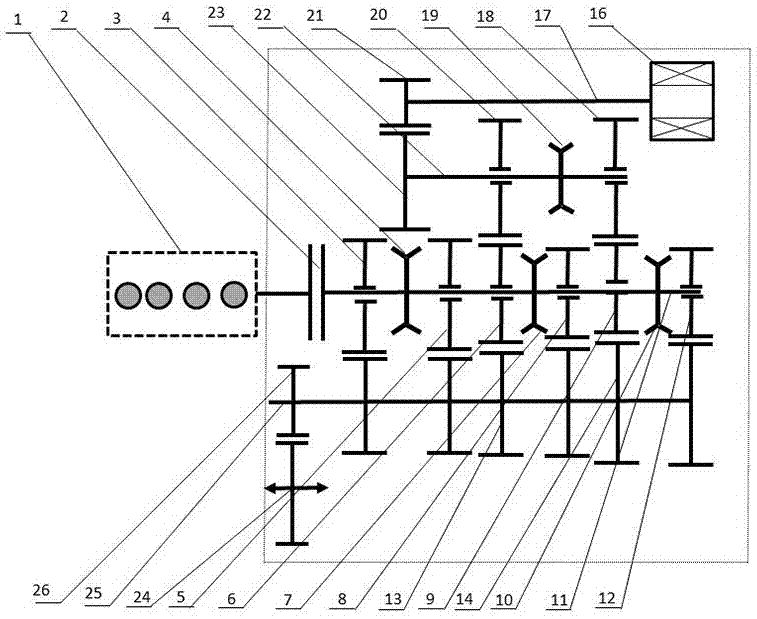
[0040] Embodiment two: see figure 2 The difference between this embodiment and the first embodiment is that the drive motor gear d is connected to the engine gear a correspondingly connected to the coupling gear c. i.e. contrast figure 1 Speaking, it is equivalent to moving the installation positions of the drive motor input shaft assembly and the drive motor shift shaft assembly from the bottom of the figure to the top of the figure. The function and performance of this embodiment are the same as those of Embodiment 1, and are figure 1 A more optimized way, the space structure is more conducive to the arrangement in the limited engine compartment.

Embodiment 3

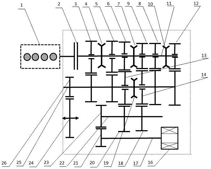
[0041] Embodiment three: see image 3 The difference between this embodiment and the first embodiment is that the synchronizers are installed on the engine input shaft 11 and the output shaft 25 respectively, and the synchronizers include the engine synchronizer e which is arranged on the engine input shaft 11 and the engine synchronizer e which is arranged on the output shaft 25 The drive motor synchronizer f on the top, the transmission gear pair can be two engine gears a or two coupling gears c, the transmission gear pair corresponding to a single engine synchronizer e is two engine gears a, and the single drive motor is synchronized The pair of transmission gears corresponding to device f is two coupling gears c.

[0042] image 3 Among them, there are three engine synchronizers e, numbered 4, 7, and 10; one drive motor synchronizer f, numbered 19; two drive motor gears d, numbered 18, 20; There are 2 coupling gears c, numbered 13, 14; 4 driven gears b; 6 engine gears a,...


PUM


Abstract

The invention discloses a hybrid coupling device based on a mechanical automatic transmission. The hybrid coupling device comprises an engine, a drive motor, a differential, synchronizers, an engine input shaft assembly, an output shaft assembly and a drive motor input shaft assembly, and further comprises a drive motor shift shaft assembly. The hybrid coupling device disclosed by the invention is compact in structure and convenient to use; the engine and the drive motor can provide sufficient power separately or in a matching manner; when outputting power, the engine input shaft assembly and the drive motor input shaft assembly simply need to respectively output power to the same output shaft assembly; the engine and the drive motor can respectively achieve different speed ratios; on the basis of guaranteeing good power output performance, the structural complexity is reduced; technical complexity and performance are well balanced; machining and assembling requirements are relatively low; output without power interruption can be achieved; the impact on parts is small during shifting; and the hybrid coupling device is low in cost input, safe and reliable, energy-saving and cost-reducing and worthy of widespread use in the technical field.

Description

technical field [0001] The invention relates to the technical field of automobile power systems, in particular to a hybrid coupling device based on a mechanical automatic transmission. Background technique [0002] With the introduction of fuel consumption limits for passenger cars in the United States, Europe, Japan and China, it is expected that the average fuel consumption of domestic passenger cars will be controlled at 5L / 100Km around 2020, and will be further controlled at 4L / 100Km around 2025. 100Km. In order to achieve the above goals, different technical routes have appeared in the research and design of passenger car power, including continuous improvement of traditional vehicles, pure electric vehicles, and plug-in hybrid / hybrid power. An important way to be more pragmatic. On the one hand, it inherits the experience and resources of previous OEMs in terms of engine / transmission system; on the other hand, with the improvement of engine efficiency and the downsiz...

Claims


Application Information

Patent Timeline
Patent Type & Authority Applications(China)
IPC IPC(8): B60K6/36B60K6/26
CPCB60K6/36B60K6/26
Inventor 朱正林
Owner 湖州伊立机械有限公司
Learn More