
Structural flexible gear speed reduction transmission structure

A flexible gear and deceleration transmission technology, applied in gear transmissions, transmissions, belts/chains/gears, etc., can solve the problems of insufficient dimensional accuracy, heavy weight, and high cost of metal materials, to ensure transmission accuracy and gear life. Effect

Inactive Publication Date: 2017-09-22
SUZHOU IND PARK KAYMAX PRECISION ENG
View PDF6 Cites 2 Cited by
  • Summary
  • Abstract
  • Description
  • Claims
  • Application Information

AI Technical Summary

Problems solved by technology

[0002] The existing gear reduction structure is generally made of metal materials. However, due to the high cost and heavy weight of metal materials, in the field of manipulators, in order to reduce costs, the transmission gears of manipulators are made of plastics. However, due to the use of plastics Injection molding or printing molding, the gears will shrink to varying degrees after cooling, that is, after the transmission gear meshing method is adopted, the corresponding connection part of the manipulator will be due to the insufficient dimensional accuracy of the plastic gears, and vibrations will occur during the gear movement, which will eventually affect Transmission accuracy and gear life

Method used


Image

  • Structural flexible gear speed reduction transmission structure
  • Structural flexible gear speed reduction transmission structure

Examples


specific Embodiment 1

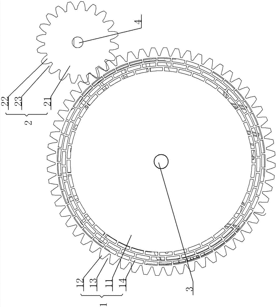
[0016] Specific embodiment one, see figure 1 : The first outer ring tooth 12, the outer ring surface formed by the first outer ring tooth groove 13 and the outer ring surface of the first body 11 are provided with a discontinuous first pore structure 14 which penetrates the first In the thickness direction of the body 11, the first air hole structure 14 has several layers arranged radially from the inner end of the first outer ring tooth 12 to the outer ring surface of the first body 11. When the second gear 2 is meshed with the first gear 1 , The second outer ring tooth 22 engages and connects to the first outer ring tooth groove 13 at the corresponding position while squeezing the first air hole structure 14 to ensure the stability of the engagement.

specific Embodiment 2

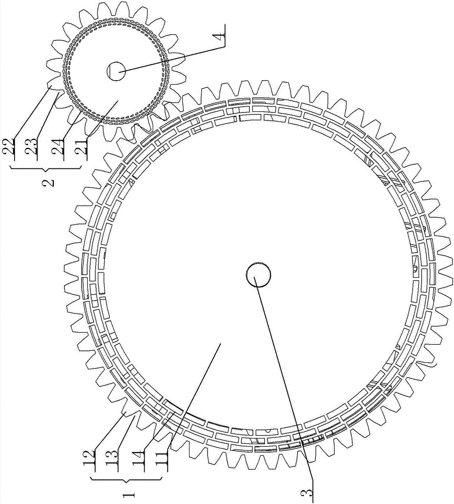
[0017] Specific embodiment two, see figure 2 : The first outer ring tooth 12, the outer ring surface formed by the first outer ring tooth groove 13 and the outer ring surface of the first body 11 are provided with a discontinuous first pore structure 14 which penetrates the first In the thickness direction of the body 11, the first pore structure 14 has several layers arranged radially from the inner end of the first outer ring tooth 12 to the outer ring surface of the first body 11. The second outer ring teeth 22 and the second outer ring A discontinuous second air hole structure 24 is provided between the outer ring surface formed by the tooth groove 23 and the outer ring surface of the second body 21. The second air hole structure 24 penetrates the thickness direction of the second body 21, and the second air hole structure 24 is The inner end of the second outer ring tooth 22 has several layers arranged radially toward the outer ring surface of the second body 21. When the...


PUM


Abstract

The invention provides a structural flexible gear speed reduction transmission structure. Plastic gears in the mutual engagement state are kept in the stable extrusion state all the time in the engagement process, stable accurate gear transmission is ensured, and the transmission precision and the gear service life are ensured; the structure comprises two plastic gears including the first gear and the second gear; a first rotating shaft is sleeved with the first gear, a second rotating shaft is sleeved with the second gear, the first gear and the second gear are arranged in an engagement connection manner, the first gear comprises a first body, a first outer ring tooth and a first outer ring tooth groove, the second gear comprises a second body, a second outer ring tooth and a second outer ring tooth groove, first air hole structures which are not continuous are arranged between the outer ring face formed by the first outer ring tooth and the first outer ring tooth groove and the outer ring face of the first body, the first air hole structures penetrate the thickness direction of the first body, and the multiple first air hole structures are arranged from the radial direction of the inner end of the first outer ring tooth to the outer ring face of the first body

Description

Technical field [0001] The invention relates to the technical field of a reduction transmission structure, in particular to a structural flexible gear reduction transmission structure. Background technique [0002] The existing gear reduction structure is generally made of metal materials. However, due to the high cost and heavy weight of metal materials, in the field of manipulators, in order to reduce costs, the transmission gears of manipulators are made of plastic. In injection molding or printing molding, the gears will shrink to different degrees after cooling. That is, after the gear meshing method of transmission is used, the corresponding connection part of the manipulator will be affected by insufficient dimensional accuracy of the plastic gear and vibration during the gear movement. Transmission accuracy and gear life. Summary of the invention [0003] In view of the above problems, the present invention provides a structured flexible gear reduction transmission struct...

Claims


Application Information

Patent Timeline
Patent Type & Authority Applications(China)
IPC IPC(8): F16H1/04F16H55/17
CPCF16H1/04F16H55/17
Inventor 蒋剑
Owner SUZHOU IND PARK KAYMAX PRECISION ENG
Learn More