
Thermal machine fatigue testing method and thermal machine fatigue testing machine adopting same

A technology of heat engine fatigue and test method, which is applied in the application of repetitive force/pulse force to test the strength of materials, measuring devices, instruments, etc., can solve the problem that the actual service conditions of hot work dies cannot be effectively met.

Active Publication Date: 2017-09-22
HENAN UNIV OF SCI & TECH
View PDF5 Cites 2 Cited by
  • Summary
  • Abstract
  • Description
  • Claims
  • Application Information

AI Technical Summary

Problems solved by technology

[0004] The purpose of the present invention is to provide a thermal engine fatigue test method to solve the problem that the test device in the prior art cannot effectively meet the actual service conditions of the hot working die due to the fact that the test device directly passes through the punch extrusion die; the purpose of the present invention It is also to provide a thermal fatigue testing machine using the test method

Method used


Image

  • Thermal machine fatigue testing method and thermal machine fatigue testing machine adopting same
  • Thermal machine fatigue testing method and thermal machine fatigue testing machine adopting same
  • Thermal machine fatigue testing method and thermal machine fatigue testing machine adopting same

Examples


Embodiment Construction

[0022] Embodiments of the present invention will be further described below in conjunction with the accompanying drawings.

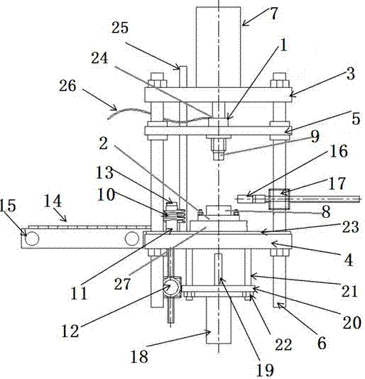
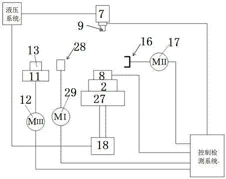
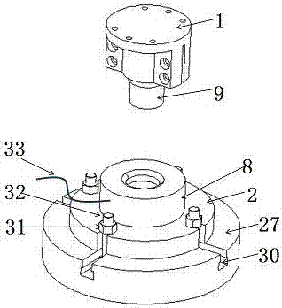
[0023] The specific embodiment of thermomechanical fatigue testing machine of the present invention, as Figure 1 to Figure 3 As shown, the testing machine is used to test the thermal fatigue effect of hot working dies. The testing machine includes a frame on which a power system, a heating system, a punch and die fixing system, and a control testing system are arranged. Wherein the die and punch fixing system includes a punch mounting seat 1 on the upper side and a die mounting seat 2 on the lower side arranged up and down on the frame, and an analog punch 9 is installed on the punch mounting seat 1, An analog die 8 is installed on the die mount 2, the frame includes a workbench 27 and a guide post 6 arranged on the workbench 27, and the guide post 6 is arranged around the punch mount 1 and the die mount 2 The four extending up and down, the guide post...


PUM


Abstract

The invention relates to a thermal machine fatigue testing method and a thermal machine fatigue testing machine adopting the same. The thermal machine fatigue testing machine comprises a machine frame, wherein a convex mould mounting base for mounting a simulating convex mould, a concave mould mounting base for mounting a simulating concave mould, and a driving device for driving the concave mould mounting base and the convex mould mounting base to perform relative motion so as to enable the simulating convex mould and the simulating concave mould to exert a pressure on blanks are arranged on the machine frame; the thermal machine fatigue testing machine further comprises a heating device for heating the blanks, a feeding device for continuously feeding the blanks to the heating device, a loading device for sending the heated blanks to a position between the simulating convex mould and the simulating concave mould , and a deloading device for deloading the pressurized blanks from the position between the simulating convex mould and the simulating concave mould. In the actual moulding process of the blanks, the blanks are heated first and then moved onto the moulds, and are moulded through mutual pressing action of the concave mould and the convex mould, so that actual service conditions of a thermal working mould are completely and effectively met, and a thermal machine fatigue result of the thermal working mould can be accurately tested.

Description

technical field [0001] The invention relates to a heat engine fatigue test method and a heat engine fatigue test machine using the method. Background technique [0002] Hot work molds are affected by both force and temperature during work. It involves the influence of various factors such as load cycle, temperature cycle, creep, friction and wear, and environmental effects, which complicates the working conditions of hot work dies. One of the main failure modes of hot work dies is thermal mechanical fatigue failure. Under the thermal mechanical load conditions of alternating cycles, due to the combined action of alternating thermal stress and mechanical stress, some points ( Especially the points on the working surface of the hot work mold) produce local permanent structural changes, and after a certain number of cycles, hot cracks, tears, bonding or fractures will be formed, which will lead to fatigue damage. The complexity of the service conditions increases the difficul...

Claims


Application Information

Patent Timeline
Patent Type & Authority Applications(China)
IPC IPC(8): G01N3/36
CPCG01N3/36G01N2203/0005G01N2203/0048G01N2203/006G01N2203/0226
Inventor 张彦敏王文超张学宾皇涛宋克兴周延军国秀花刘亚民郜建新龙伟民王要利宋宇刘建波
Owner HENAN UNIV OF SCI & TECH
Learn More