Device and method for debugging and testing transmission and reception of optical module at the same time

An optical module, a technology for receiving light, applied in electromagnetic wave transmission systems, electrical components, transmission systems, etc., can solve the problems of low equipment utilization, long debugging time, low efficiency, etc., to achieve high equipment utilization, short debugging time, Efficient effect

Pending Publication Date: 2017-09-22
SHENZHEN JIXIANG TENGDA TECH
View PDF9 Cites 5 Cited by
  • Summary
  • Abstract
  • Description
  • Claims
  • Application Information

AI Technical Summary

Problems solved by technology

[0002] The transmission and reception of the traditional commissioning optical module are commissioned sequentially in time, and it is impossible to commission the transmission and reception of the optical module at the same time. The commissioning time is long, the equipment utilization rate is low, and the efficiency is low.

Method used


Image

  • Device and method for debugging and testing transmission and reception of optical module at the same time
  • Device and method for debugging and testing transmission and reception of optical module at the same time
  • Device and method for debugging and testing transmission and reception of optical module at the same time

Examples


Embodiment Construction

[0035] The present invention will be further described below in conjunction with the description of the drawings and specific embodiments.

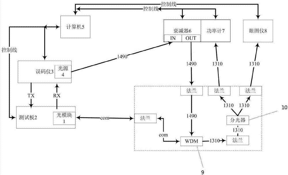
[0036] like figure 1 As shown, a device for simultaneously commissioning and testing the transmission and reception of an optical module, including an optical module 1, a test board 2, a bit error meter 3, a computer 5, an attenuator 6, a power meter 7, an eye diagram instrument 8, and a wavelength division multiplexing Unit (WDM) 9 and optical splitter 10, wherein the test board 2, bit error meter 3, attenuator, 6 power meter 7, and eye diagram meter 8 are respectively connected to the computer 5 through control lines, and the test board 2 is connected to the BER tester 3, the optical module 1 is connected to the test board 2, the optical module 1 is connected to the wavelength division multiplexing unit 9, and the BER tester 3 is provided with a light source 4 , the received light emitted by the light source 4 is transmitted to the wav...


PUM


Abstract

The invention provides a device for debugging and testing transmission and reception of an optical module at the same time. The device comprises the optical module, a test board, a bit error ratio tester, a computer, an attenuator, a power meter, an eye diagram device, a wavelength division multiplexing unit and an optical splitter. The test board, the bit error ratio tester, the attenuator, the power meter and the eye diagram device are connected with the computer through control lines. The test board is connected with the bit error ratio tester. The optical module is connected with the test board. The optical module is connected with the wavelength division multiplexing unit. A light source is arranged on the bit error ratio tester. Reception light emitted by a light source is transmitted to the wavelength division multiplexing unit through the attenuator. The reception light is transmitted to the optical module through the wavelength division multiplexing unit. The invention also provides a method for debugging and testing transmission and reception of the optical module at the same time. The method and the device have the beneficial effects that the transmission and reception of the optical module can be debugged and tested at the same time, the debugging time is short, a device utilization ratio is high, and the efficiency is high.

Description

technical field [0001] The invention relates to commissioning and testing of optical modules, in particular to a device and method for simultaneously commissioning and testing the transmission and reception of optical modules. Background technique [0002] The transmission and reception of the traditional commissioning optical module are commissioned sequentially in time, and it is impossible to commission the transmission and reception of the optical module at the same time. The commissioning time is long, the utilization rate of the equipment is low, and the efficiency is low. Contents of the invention [0003] In order to solve the problems in the prior art, the present invention provides a device and method for simultaneously commissioning and testing the transmission and reception of an optical module. [0004] The invention provides a device for simultaneously debugging and measuring the transmission and reception of an optical module, including an optical module, a ...

Claims


Application Information

Patent Timeline
Patent Type & Authority Applications(China)
IPC IPC(8): H04B10/079
CPCH04B10/079
Inventor 吴晓叶炳华彭应明赵恒
Owner SHENZHEN JIXIANG TENGDA TECH
Why Eureka
Try Eureka