Waste iron pulverizer

A pulverizer and pulverizing mechanism technology, applied in the industrial field, can solve the problems of substandard iron, insufficient pulverization, lack of secondary pulverizing devices, etc., and achieve the effect of reducing the scrap rate and improving the pulverization efficiency.

Inactive Publication Date: 2017-09-26
王晓东
View PDF7 Cites 3 Cited by
  • Summary
  • Abstract
  • Description
  • Claims
  • Application Information

AI Technical Summary

Problems solved by technology

[0002] At present, the existing crushers will have the problem of insufficient crushing, and the

Method used


Image

  • Waste iron pulverizer
  • Waste iron pulverizer
  • Waste iron pulverizer

Examples


Example Embodiment

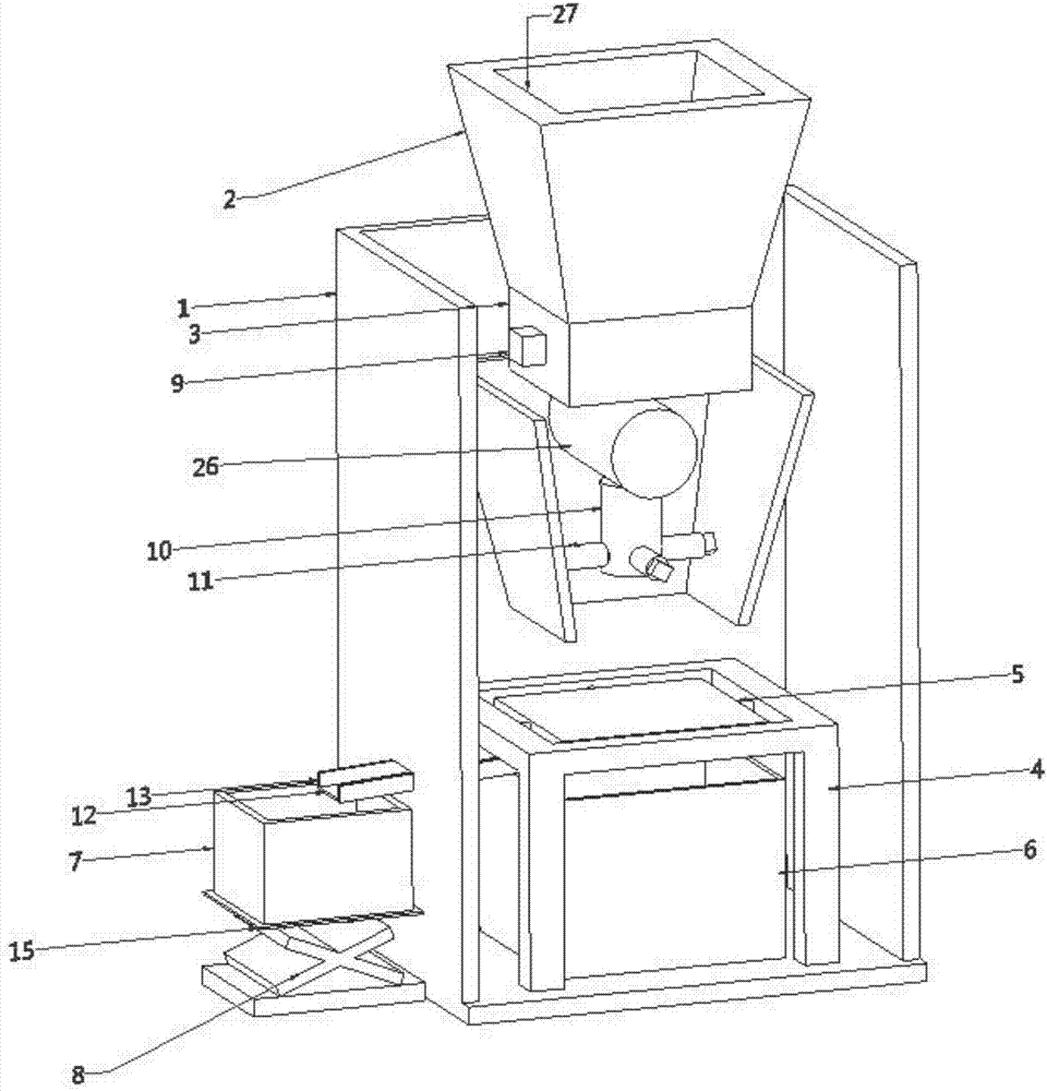
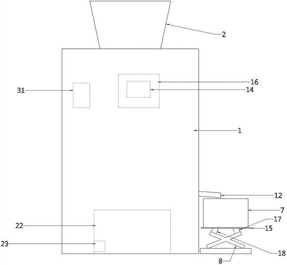
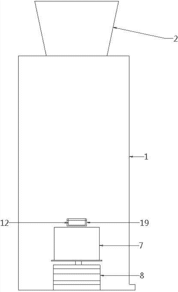
[0021] The present invention will be described in detail below with reference to the drawings, such as Figure 1-6 A scrap iron crusher is shown, comprising a body (1), a feeding hopper (2) is installed at the upper end of the body (1), and a feeding pipe (3) is installed at the lower end of the feeding hopper (2), so A crushing mechanism is installed at the lower end of the feeding pipe (3), a screen bracket (4) is placed on the inner bottom surface of the body (1), and a vibration motor (24) is installed on the right side of the bracket (4). The inside of the screen support (4) is equipped with a screen (5), the inside of the support (4) and the outside of the screen (5) are connected by a spring structure, and a plc placement slot (14) is opened on the back of the body (1) ), a plc controller (16) is placed in the plc placement slot (14), a square hole (20) is opened on the right side of the fuselage (1), and the square hole (20) is placed in the storage box (6) A groove (1...


PUM


Abstract

The invention discloses a scrap iron pulverizer, which comprises a fuselage, a feeding hopper is installed at the upper end of the fuselage, a feeding pipe is installed at the lower end of the feeding hopper, a crushing mechanism is installed at the lower end of the feeding pipe, and a crushing mechanism is installed at the lower end of the feeding pipe. A screen bracket is placed on the inner bottom surface, the inside of the screen bracket is equipped with a screen, the inside of the bracket is connected to the outside of the screen through a spring structure, and a plc placement slot is opened on the rear side of the fuselage, and the plc placement slot Put the plc controller in it, there is a square hole on the right side of the fuselage, the square hole is put into the storage box, there is a groove on the left side of the fuselage, and an iron box is placed at the lower end of the groove, The bottom surface of the iron box is equipped with a lifting mechanism, and the bottom of the screen is equipped with an inclined transmission plate. The baffles are welded on both sides of the transmission plate, and the iron plate for placing the iron box is welded on the top of the lifting mechanism. The iron plate The bottom is equipped with a turning mechanism. The invention has the advantages of simple structure and strong practicability.

Description

Technical field [0001] The invention relates to the industrial field, in particular to a scrap iron grinder. Background technique [0002] The existing crushers all have the problem of insufficient crushing, and the crushed iron blocks may not meet the standards and lack a secondary crushing device. Summary of the invention [0003] The purpose of the present invention is to solve the above-mentioned problems and design a scrap iron grinder. The technical solution of the present invention to achieve the above objective is a scrap iron grinder, including a body, a feeding hopper is installed at the upper end of the body, a feeding pipe is installed at the lower end of the feeding hopper, and a crusher is installed at the lower end of the feeding pipe. Mechanism, a screen bracket is placed on the inner bottom surface of the fuselage, a vibration motor 1 is installed on the right side of the bracket, a screen is installed on the inside of the screen bracket, and the inside of the br...

Claims


Application Information

Patent Timeline
IPC IPC(8): B02C13/18B02C13/28B02C13/284B02C13/286
CPCB02C13/18B02C13/2804B02C13/284B02C13/286B02C2013/28609B02C2013/28618B02C2201/06
Inventor 王晓东
Owner 王晓东
Why Eureka
Try Eureka