Waterline cutter for valve seat

A water line and cutting tool technology, which is applied in the direction of cutting tools, cutting blades, manufacturing tools, etc. used in lathes, can solve the problems of time-consuming processing, increasing costs, wasting economic resources, etc., and achieve the effect of good fastening effect and convenient operation

Inactive Publication Date: 2017-09-26
GLOBAL SET VALVE COMPONENTS JIANGSU
View PDF0 Cites 0 Cited by
  • Summary
  • Abstract
  • Description
  • Claims
  • Application Information

AI Technical Summary

Problems solved by technology

However, larger grooves can also be easily processed by CNC machine tools, while waterline processing lacks a practical and efficient processing too

Method used


Image

  • Waterline cutter for valve seat
  • Waterline cutter for valve seat

Examples


Embodiment Construction

[0018] The implementation of the present application will be described in detail below with reference to the accompanying drawings and examples, so as to fully understand and implement the implementation process of how the present application uses technical means to solve technical problems and achieve technical effects.

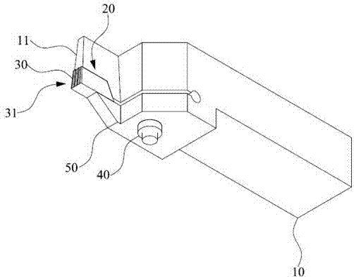
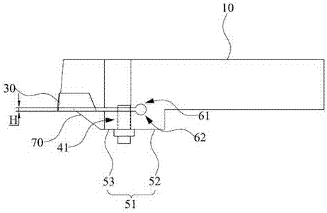
[0019] Please refer to figure 1 , figure 1 It is a three-dimensional view of the waterline cutter for the valve seat of the embodiment of the present application. As shown in the figure, a valve seat waterline cutter includes a handle 10; a cutter head 11 located at one end of the handle 10; a cutter groove 20 arranged on the cutter head 11; a waterline blade welded to the cutter groove 20 30; and press the clamp part 50 of the waterline blade 30 through the fastening bolt 40, and one end of the clamp part 50 is connected to the handle 10. In one embodiment of the present invention, the knife handle 10 is equipped with a knife slot 20 for welding the water...


PUM


Abstract

The application discloses a waterline cutter for a valve seat, which includes a handle; a cutter head located at one end of the handle; a cutter groove provided on the cutter head; a waterline blade welded to the cutter groove; The bolt presses the clamp portion of the waterline blade, and one end of the clamp portion is connected to the knife handle. The present invention utilizes the waterline blade with the waterline groove, can process the waterline, and is convenient to operate; at the same time, the clamp part adopts fastening bolts to fasten the pressure plate, and the fastening effect is better.

Description

technical field [0001] The application belongs to the technical field of valve processing, and in particular relates to a waterline cutter for a valve seat. Background technique [0002] At present, in order to improve the performance of the valve seat on the market, grooves of different sizes need to be processed not only on the surface of the valve seat, but also on the outer end surface, some of which are used to fit the sealing ring to ensure the sealing performance; and limited waterlines are arranged for processing needs , to facilitate hydrophobicity and improve the fluidity of the medium. However, larger grooves can also be easily processed by CNC machine tools, while waterline processing lacks a practical and efficient processing tool. At this time, the manufacturer also has to increase the cost, and realize it by wire cutting, which is time-consuming and wastes economic resources. Contents of the invention [0003] In view of this, the technical problem to ...

Claims


Application Information

Patent Timeline
IPC IPC(8): B23B27/06B23B27/16
CPCB23B27/06B23B27/164B23B2205/04
Inventor 魏瑞福
Owner GLOBAL SET VALVE COMPONENTS JIANGSU
Why Eureka
Try Eureka