
Power soil arch model testing system and method based on transparent soil technology

A model test and transparent soil technology, applied in the direction of testing material strength by applying repetitive force/pulsation force, testing material strength by applying stable tension/compression, and measuring devices, etc., can solve the problem of not being able to fully reflect soil deformation, etc. problems, achieve high-precision real-time measurement, and improve test efficiency

Inactive Publication Date: 2017-09-26
TONGJI UNIV
View PDF4 Cites 24 Cited by
  • Summary
  • Abstract
  • Description
  • Claims
  • Application Information

AI Technical Summary

Problems solved by technology

[0004] The main indoor test method for soil arching effect is Terzaghi's "trapdoor" test [1] At present, the observation surface of the test is an outer surface of the model. Due to the influence of the side wall effect of the model box, the observation results on the surface cannot completely reflect the soil deformation caused by the "soil arch effect" inside the soil.

Method used


Image

  • Power soil arch model testing system and method based on transparent soil technology
  • Power soil arch model testing system and method based on transparent soil technology
  • Power soil arch model testing system and method based on transparent soil technology

Examples


Embodiment

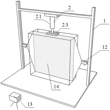
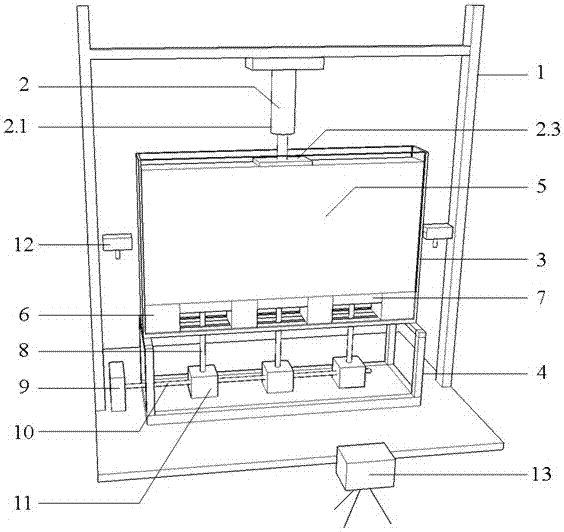
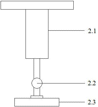
[0043] Example 1: see figure 1 — Figure 8, a dynamic soil arch test system based on transparent soil technology, consisting of loading device 2, model tank 3, transparent soil 5, fixed block 6, movable block 7, worm gear box 11, laser transmitter 12 and high-speed camera 13 and other parts composition. The base of the reaction force frame 1 is anchored on the bottom surface; the model support 4 is placed in the center of the base and fixed; the reaction force beam is adjusted to a suitable height, and the two ends of the reaction force beam are fixed on the column 1.2 with screws; the loading device 2 is fixed on the reaction force Beam center; the model slot 3 is placed on the model support 4, four identical rectangular fixed blocks 6 and three identical rectangular movable blocks 7 are made of transparent plexiglass, the length of the movable block 7 is twice that of the fixed block 6, and the width is equal to The inner width of the model groove 3, the height of the fixe...


PUM


Abstract

The e invention relates to a power soil arch model testing system and method based on a transparent soil technology. The testing system comprises a reaction frame, a loading device, a model bracket, a vertical sliding screw, a worm gear case body, a horizontal connecting shaft, an electric motor, a laser emitter and measurement equipment; fixed blocks and movable blocks are mounted at the bottom of a model groove; the model groove can perform relative displacement to the fixed blocks by shifting the movable blocks after being provided with transparent soil, and forms stable soil arches in the transparent soil; the loading device is mounted on the reaction frame, so as to perform power loading and simulate the influence on the soil arches by power load. The method comprises the steps of determining the sizes and quantity of required fixed blocks and movable blocks, mounting and sealing the fixed blocks and movable blocks, mounting the electric motor, the horizontal connecting shaft, the vertical sliding screw and the worm gear case body, drawing the movable blocks to move, simulating situations of positive and negative soil arches and different quantity of soil arches, fixing the movable blocks after the soil arches are formed, performing power loading through the loading device, shooting laser speckle field through a high-speed camera during testing, and analyzing rules of the formation of the soil arches and evolution of the soil arches under dynamic load.

Description

technical field [0001] The invention relates to a model test system and method in the technical field of geotechnical engineering, in particular to a dynamic soil arch model test system and method based on transparent soil technology. Background technique [0002] In the soft soil area, due to the high compressibility and low strength of the soil, in order to reduce the total settlement and unevenness of the roadbed, vertical reinforcements are often used in engineering to strengthen the soft soil roadbed. During the process of embankment filling and line operation, due to the difference in stiffness of the soil between the piles of the vertical reinforcement, uneven settlement will occur on the surface of the embankment. The shear stress in the embankment filling will cause the load borne by the soil between the piles to gradually transfer to the piles. This transfer law is called "soil arch effect". The formation of complete soil arch in embankment fill is the key to elim...

Claims


Application Information

Patent Timeline
IPC IPC(8): G01N3/32G01N3/08G01N3/06G01B11/16
CPCG01N3/32G01B11/16G01N3/068G01N3/08G01N2203/0003G01N2203/0005G01N2203/0019G01N2203/0075G01N2203/0647G01N2203/0676G01N2203/0682
Inventor 张振陶凤娟叶观宝韩杰刘鎏
Owner TONGJI UNIV
Learn More