Bell cup or guide-air ring including barrier coating

An air ring, bell cup technology, applied in coatings, devices for coating liquid on surfaces, electrostatic spray devices, etc., can solve problems such as high risk of fire

Active Publication Date: 2021-01-12
DUERR SYST GMBH
View PDF15 Cites 0 Cited by
  • Summary
  • Abstract
  • Description
  • Claims
  • Application Information

AI Technical Summary

Problems solved by technology

In this case, the risk of fire is particularly high

Method used


Image

  • Bell cup or guide-air ring including barrier coating
  • Bell cup or guide-air ring including barrier coating
  • Bell cup or guide-air ring including barrier coating

Examples


Embodiment Construction

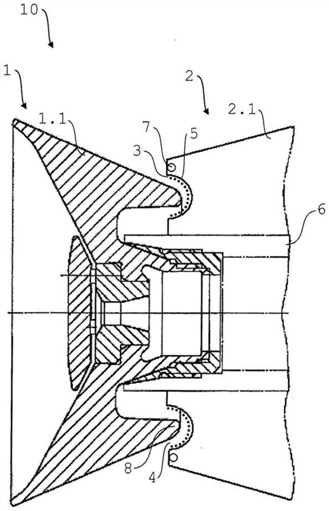
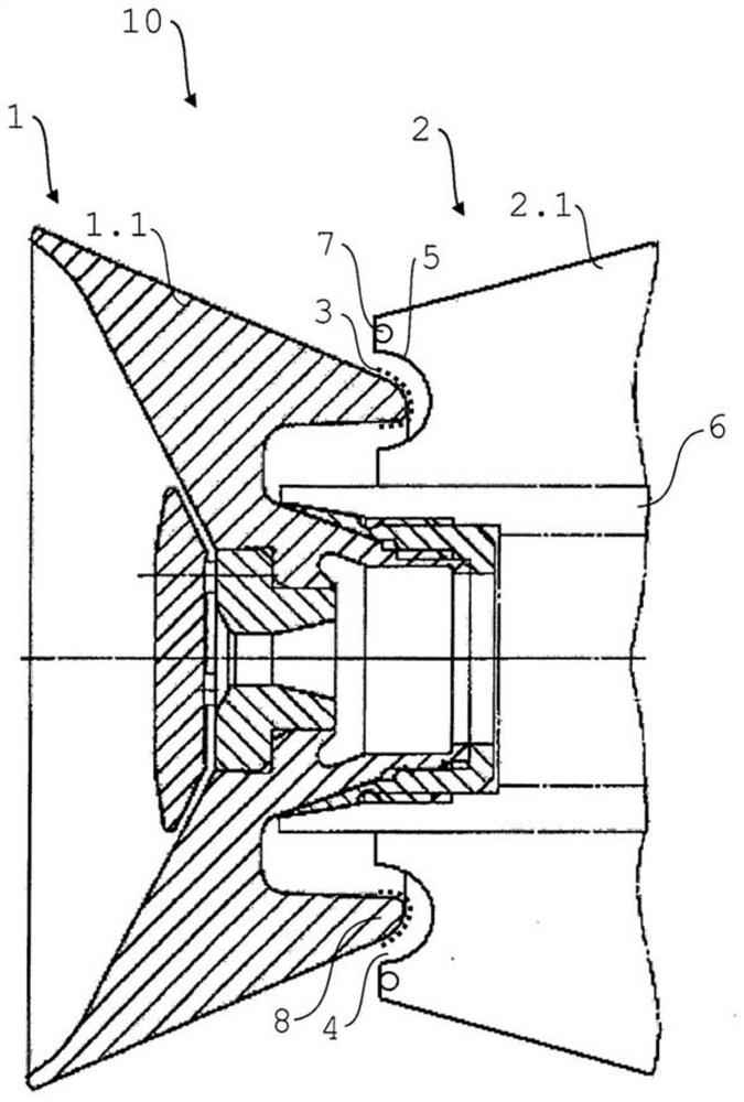
[0079]The embodiments shown in the drawings partially overlap, so for the sake of explanation, similar or identical components have the same reference signs, and the description of other embodiments is also referred to to avoid repetition.

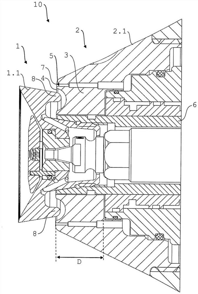
[0080]figure 1 It is a cross-sectional view of an electrostatic rotary atomizer 10 used for painting a motor vehicle body and / or its additional parts. The rotary atomizer 10 includes a bell cup 1 for atomizing paint and for delivering a spray jet of paint, and the bell cup 1 rotates during operation. The rotary atomizer 10 also includes a guide-air ring 2 for conveying a guide-air flow from the guide-air discharge port 7 to shape the spray jet of paint delivered through the bell cup 1. The guide-air ring 2 is during operation Does not rotate. The bell cup 1 is arranged in front of the guide-air ring 2. The guide-air ring 2 corresponds to an embodiment of the present invention, and the bell cup 1 can be basically designed according to the prior art....


PUM

PropertyMeasurementUnit
widthaaaaaaaaaa
thicknessaaaaaaaaaa
thicknessaaaaaaaaaa

Abstract

The invention relates to a coating plant component (1; 2) for a suitable electrostatic rotary atomizer (10). The coating device part (1; 2) is a bell cup (1) or an atomizer ring (2). The coating plant part (1; 2) comprises a metallic base body (1.1; 2.1) and is characterized in particular in that the metallic base body (1.1; 2.1) is provided with a non-metallic material (3). The invention also relates to an associated method for applying a non-metallic material (3) to a coating plant component (1; 2).

Description

Technical field[0001]The present invention relates to a coating equipment part for a rotary atomizer, wherein the coating equipment part is provided with a non-metallic material for avoiding sparks. The coating equipment component can be a bell cup. The coating device component can be a guide-air ring.Background technique[0002]For general prior art, you can first refer to DE 102009013979 A1, DE 102008027997 A1 and US2010 / 0211205 A1.[0003]Rotary atomizers for spraying motor bodies and their additional components are known in the prior art in a variety of different forms. This type of rotary atomizer usually includes a metal bell cup that rotates during operation for atomizing paint and for conveying paint spray jets, and a non-rotating metal bell cup for conveying guide-air flow to shape paint spray jets during operation Metal boot-air ring. There is also a guide-air ring made of plastic. These are used in the case of external loading (conductive paint), for example. The disadvantage...

Claims


Application Information

Patent Timeline
Patent Type & Authority Patents(China)
IPC IPC(8): B05B5/04B05D5/12B05D3/00B05D1/00B05D1/02
CPCB05B5/0403B05B5/0407B05B5/0426B05D1/00B05D1/02B05D3/002B05D5/12B05B15/14B05B5/081B24C1/00C08L101/00
Inventor B·塞茨M·鲍曼H-J·诺尔特
Owner DUERR SYST GMBH
Why Eureka
Try Eureka