Self-cooling cable trench for communication base station

A communication base station and self-cooling technology, which is applied in cable installation, ground cable installation, electrical components, etc., can solve problems such as heat dissipation difficulties, achieve the effect of improving cooling effect, reducing labor maintenance costs, and good heat dissipation and cooling effect

Inactive Publication Date: 2021-01-08
湖州浪佩智能科技有限公司
View PDF0 Cites 2 Cited by
  • Summary
  • Abstract
  • Description
  • Claims
  • Application Information

AI Technical Summary

Problems solved by technology

[0005] The object of the present invention is to provide a self-cooling cable trench for communication base stations with good heat dissipation function for the above-mentioned difficult problem of heat dissipation.

Method used


Image

  • Self-cooling cable trench for communication base station
  • Self-cooling cable trench for communication base station

Examples


Embodiment 1

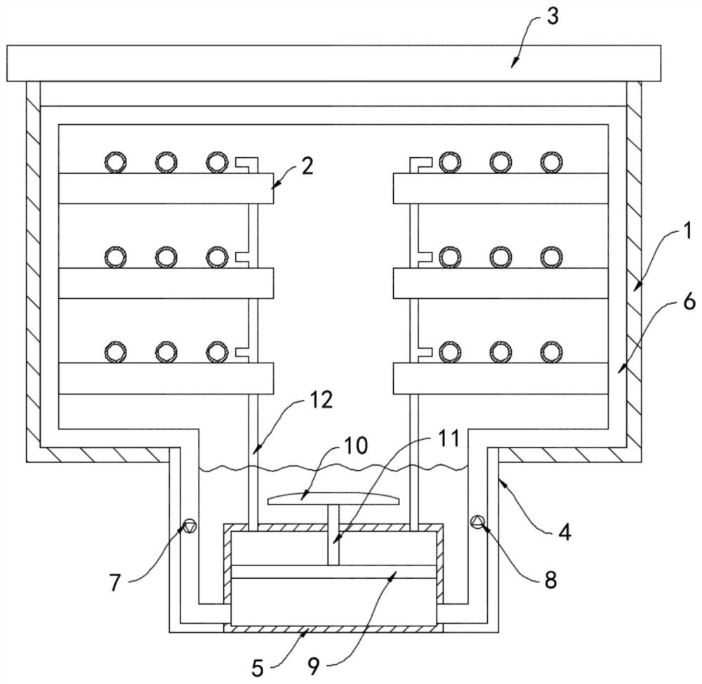
[0020] Such as figure 1 As shown, a communication base station uses a self-cooling cable ditch, including a ditch body 1, a cable frame 2 and a cover plate 3. The bottom of the ditch body 1 is provided with a drainage channel 4 extending longitudinally along the ditch body 1, and the drainage channels 4 are connected in series. In the urban sewage discharge system, when the sewage flows in the drainage ditch 4, it can quickly take away the heat in the ditch body 1 to achieve a good cooling effect. Cooling liquid pipe 6 is installed on the top, and the cooling liquid pipe 6 is filled with cooling liquid, and the cooling liquid is water. One-way liquid inlet valve 7 and one-way liquid discharge valve 8 are respectively installed at both ends of 6. One-way liquid inlet valve 7 only allows the coolant in coolant pipe 6 to enter circulation box 5, and one-way liquid discharge valve 8 only allows The coolant in the circulation tank 5 is allowed to drain into the coolant pipe 6 .

...

Embodiment 2

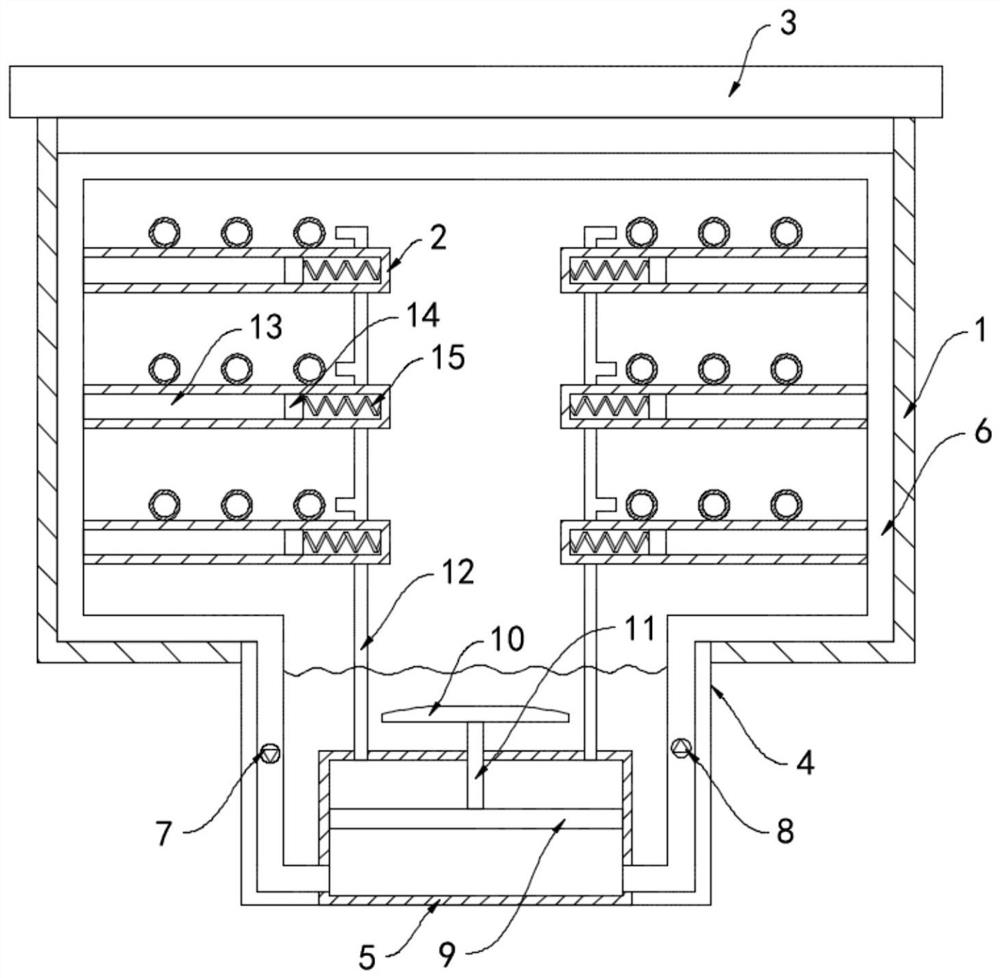
[0026] Such as figure 2 As shown, the difference between this embodiment and Embodiment 1 is that: the cable rack 2 is provided with a cavity 13, the cavity 13 communicates with the cooling liquid pipe 6, and the cavity 13 is sealed and slidably connected with a sealing slider 14, The sealing slider 14 is fixedly connected to the side wall of the cavity 13 through the memory spring 15. The memory spring 15 is wound by a CuZnAl memory alloy wire. It is in a natural state at room temperature. When the temperature is higher than 65°C, it reaches its transformation temperature. Time memory spring 15 is in shortened state.

[0027] In this embodiment, when the surface temperature of the cable rack 2 is too high and reaches the metamorphic temperature of the memory spring 15, the memory spring 15 shrinks and drives the sealing slider 14 to slide, and the cooling liquid in the cooling liquid pipe 6 is sucked into the cavity 13, quickly reduce the internal temperature of the cable r...


PUM


Abstract

The invention belongs to the field of cable trench wells, and particularly relates to a self-cooling cable trench for a communication base station. The self-cooling cable trench comprises a trench body, a cable rack and a cover plate, wherein the bottom of the trench body is provided with a drainage channel extending along the longitudinal direction of the trench body, the drainage channel is connected in series in an urban sewage discharge system, the bottom of the drainage channel is provided with a circulating box, a cooling liquid pipe is installed on the inner side wall of the trench body, the two ends of the cooling liquid pipe extend into the drainage channel and communicate with the bottom of the circulating box, a one-way liquid inlet valve and a one-way liquid outlet valve are installed at the two ends of the cooling liquid pipe correspondingly, a horizontally-arranged piston plate is connected to the inner side wall of the circulating box in a sealed and sliding mode, and awing plate is arranged above the circulating box and is fixedly connected with the piston plate through a connecting rod. According to the invention, water flow in a drainage channel can drive a wingplate to move up and down, so that circulating flow of cooling liquid is achieved, the good heat dissipation and cooling effect is achieved, energy conservation and environmental protection are achieved, and the manual maintenance cost is reduced.

Description

technical field [0001] The invention belongs to the field of cable trenches, in particular to a self-cooling cable trench for communication base stations. Background technique [0002] Cable trench is an underground pipeline for laying and replacing power or communication cable facilities, and it is also an enclosure structure for cable facilities. There are rectangular, circular, arched and other pipeline structures. The advantages of cable trench laying are similar to cable pipes laying, and does not need to go into the well, which reduces investment. Most communication base stations are equipped with cable trenches for cable laying. [0003] The interior of the traditional cable trench is relatively closed, and the heat generated by the cable during work is difficult to dissipate in time. The cable works at high temperature for a long time, which accelerates the rapid aging and peeling of the outer insulation skin, and the maintenance cost is high, and it is easy to cause...

Claims


Application Information

Patent Timeline
Patent Type & Authority Applications(China)
IPC IPC(8): H02G9/02H05K7/20H02G3/03
CPCH02G3/03H02G9/02H05K7/20145H05K7/20272
Inventor 王云
Owner 湖州浪佩智能科技有限公司
Why Eureka
Try Eureka