Life rope fixator

A technology of life rope and fixing frame, which is applied in the direction of construction, building structure, and building material processing, etc. It can solve the problems that the safety rope cannot be used for high-hanging and low-hanging, cannot meet the needs of high-altitude operations, and increase labor and material costs. , to achieve good promotion and application prospects, eliminate hidden dangers of operation safety, and simple structure

Inactive Publication Date: 2017-09-29
CHINA MCC5 GROUP CORP
View PDF6 Cites 2 Cited by
  • Summary
  • Abstract
  • Description
  • Claims
  • Application Information

AI Technical Summary

Problems solved by technology

The first fixing method is the most used at present, but its disadvantage is that the angle steel is directly welded on the steel beam. After use, gas cutting, welding scar grinding, and paint repair are required. The process is cumbersome, and additional labor and material costs are added.
The second fixing method is relatively seldom used. Its disadvantage is that it cannot meet the requirements of the safety code that the safety rope must be hung high and low. It has safety risks and cannot meet the needs of high-altitude operations.

Method used


Image

  • Life rope fixator
  • Life rope fixator
  • Life rope fixator

Examples


Embodiment 1

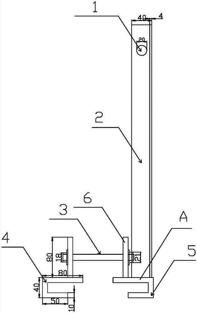
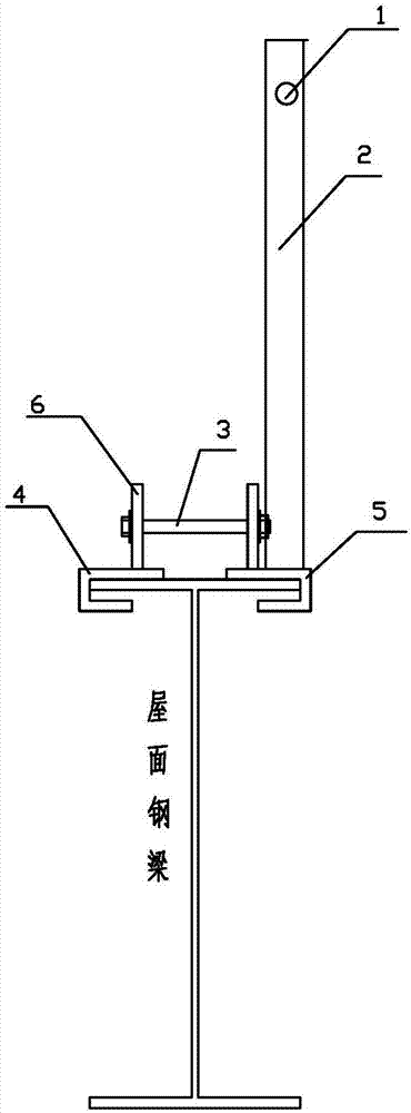
[0023] see figure 1 , the lifeline fixture of this embodiment includes clamps 4 and 5 with a U-shaped vertical section, each of the clamps 4 and 5 has a connecting plate 6 welded vertically to the end surface A on the outside of each of the clamps 4 and 5. The positions of the connecting plates correspond to each other and are provided with corresponding holes. The outside of the end face A of the clamp 5 also has an angle steel 2 welded vertically to the end face. The life rope penetration hole 1 is opened on the angle steel 2 . When in use, use the state diagram to see figure 2 , put the roof steel beams in the U-shaped openings of fixtures 4 and 5, select bolts 3 of appropriate size to fix the connection plate 6 through the holes on it, and insert the life rope into the life rope penetration hole 1, thus completing the installation of the life rope fixed. After the fastening is completed, it can be put into use. After waiting for use, take off the bolt 3, and the fixing...

Embodiment 2

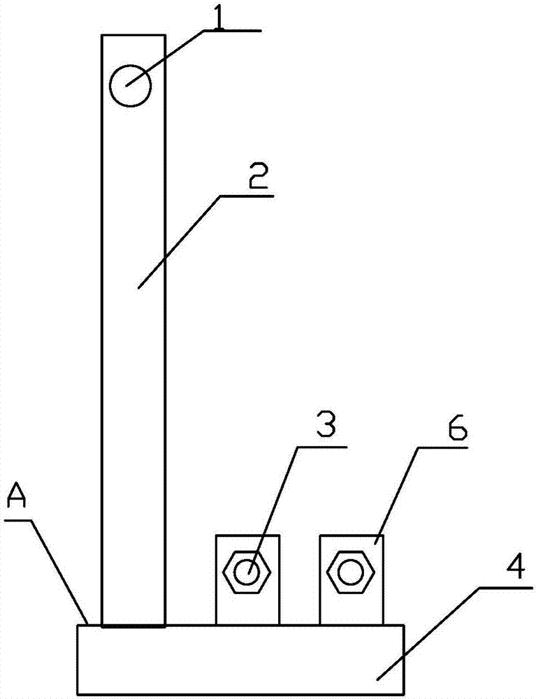
[0025] see figure 1 and image 3 , the life rope holder of the present embodiment, the clamps 4 and 5 have the same structure and shape, and the upper end surface A of each clamp has two (or more than two) connecting plates 6 vertically welded to the end surface, and the clamps 4 and 5 The positions of the connecting plates are corresponding, and corresponding holes are provided. There is also an angle steel 2 vertically welded to the end surface on the outside of the end face A. The life rope penetration hole 1 is opened on the angle steel 2. The angle steel 2 on the clamps 4 and 5, And the life rope piercing hole 1 on the angle steel 2 is relatively. When in use, the roof steel beams are placed in the U-shaped openings of the fixtures 4 and 5, and the two pairs of connecting plates 6 are fixedly connected with the bolts 3 of appropriate sizes through the holes on them respectively, and the life ropes penetrate the life ropes of the two angle steels 2. Enter hole 1, promptl...

Embodiment 3

[0027] see Figure 4 The difference between the life rope fixing frame of this embodiment and Embodiment 1 is that the clamps 4 and 5 are respectively connected by the upper end face splint A-1 and the lower end face splint A-2 through bolts 3 to form a U-shaped vertical section. Fixture, all the other are identical with embodiment 1. See embodiment 1 and 2 for using process.


PUM


Abstract

The invention discloses a life rope fixator, comprising clamps 4 and 5 having a U-shaped vertical section; the outer side of one end of each of the clamps 4 and 5 is provided with connection plate 6 vertically fixed to the end, the outer side of the end A of the clamp 4 or 5 is also provided with steel angle 2 vertically fixed to the end, the steel angle 2 is provided with life rope insertion hole 1, and the connection plates 6 on the clamps 4 and 5 are connected in releasable manner. In use of the life rope fixator, a roof steel beam is placed in U-shaped openings of the clamps 4 and 5, the clamps 4 and 5 are then fastened in releasable manner, the roof steel beam is firmly fixed in the two opposing U-shaped openings, a life rope is passed through the life rope insertion hole 1, and accordingly the life rope is fixed. When the life rope fixator is idle, the clamps 4 and 5 are separated. The life rope fixator is simple in structure, convenient to operate, low in cost and convenient to use, is suitable for long-term use after single investment, is friendly to the surface of a steel beam, and may serve as a good life rope fixing manner for the industry of modern buildings.

Description

technical field [0001] The invention belongs to the field of construction, and in particular relates to a life rope fixing frame that needs to be frequently used in the construction industry. Background technique [0002] In the construction industry, especially the modern construction industry, working at heights is extremely common and unavoidable. Construction workers need to use life ropes for safety protection when working at heights to avoid falling. [0003] At present, there are two conventional ways of fixing the life rope in the construction industry. The first is to directly weld the angle steel on the steel beam, and then tie one end of the life rope to the angle steel; the second is to directly tie the life rope to both ends. On the short pillars of the parapet wall. The first fixing method is the most used at present, but its disadvantage is that the angle steel is directly welded on the steel beam. After use, gas cutting, welding scar grinding, and paint repa...

Claims


Application Information

Patent Timeline
Patent Type & Authority Applications(China)
IPC IPC(8): E04G21/32
CPCE04G21/328
Inventor 刘俊
Owner CHINA MCC5 GROUP CORP
Why Eureka
Try Eureka