Matrix switch relay fault detection device and method
A technology for relay faults and matrix switches, which is applied to measuring devices, circuit breaker tests, instruments, etc., can solve the problems of long voltage measurement or resistance measurement, low detection efficiency, and long detection time of matrix switch faults, etc., to achieve Shorten the fault detection time, the effect is obvious, and the effect of improving the detection efficiency
- Summary
- Abstract
- Description
- Claims
- Application Information
AI Technical Summary
Problems solved by technology
Method used
Image
Examples
Embodiment 1
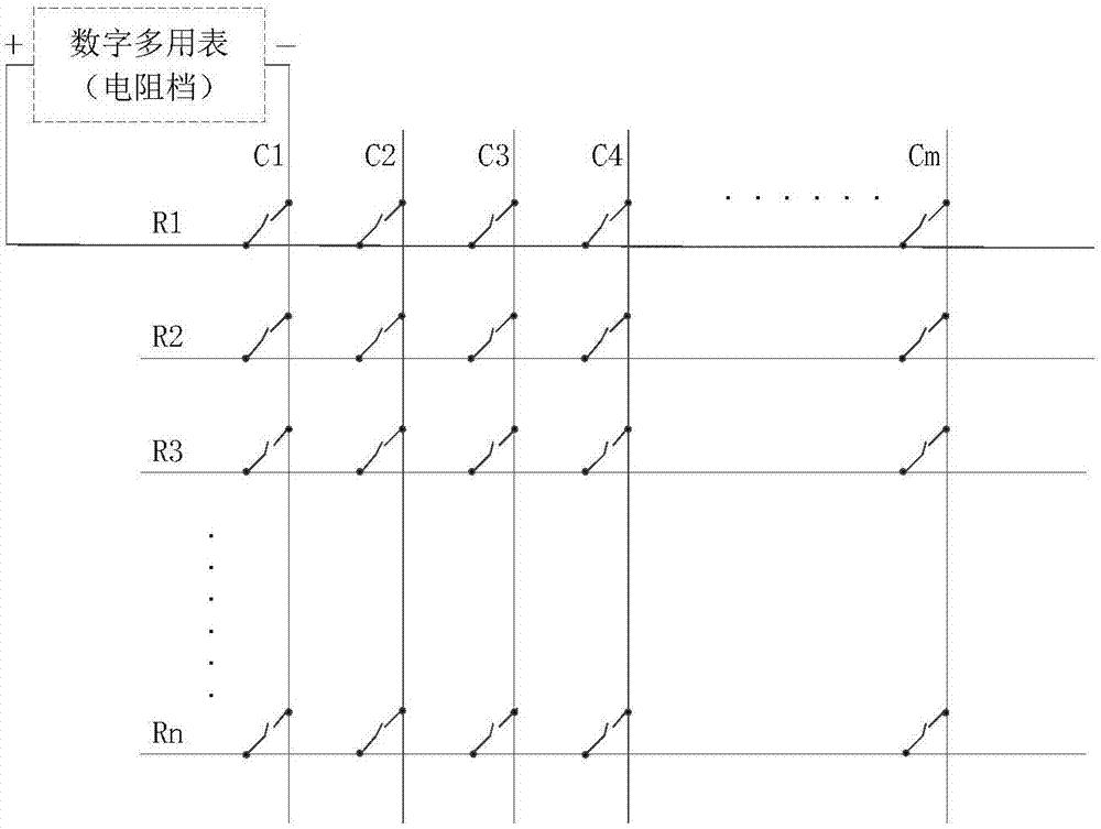
[0029] combine Figure 4 , a matrix switch relay fault detection device, including a circuit board 1, the circuit board is provided with a connector 2, a first port A and a second port B, and all signal input terminals and all signal output terminals of the matrix switch are connected to On the connector 2, all signal input terminals of the matrix switch connected to the connector 2 are connected to the first port A, and all signal output terminals of the matrix switch connected to the connector 2 are connected to a resistor The other ends of the resistors are connected to the second port B, and a digital multimeter is connected between the first port and the second port.
Embodiment 2
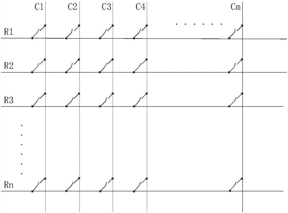
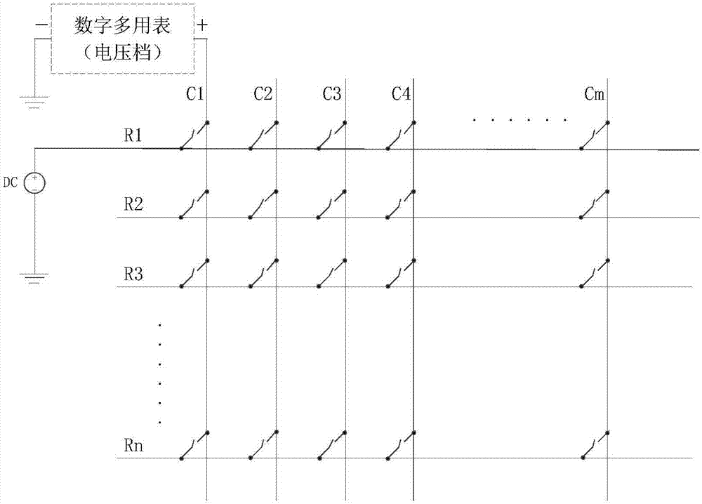
[0031] The detection method of a kind of matrix switch relay failure detection device of above-mentioned embodiment 1, wherein, the matrix switch is the single line matrix switch of n*m mode, n is the number of rows, m is the number of columns, and the resistance value of each resistor is x, The value of x is relatively large, and x is from 100 kohms to 10 megohms. The value of x can be changed according to actual operation requirements, and is not necessarily limited to the above range.
[0032] The detection method comprises the following steps:
[0033] Step 1: Close the relays connected to the signal input terminals in the first row of the matrix switch and the signal output terminals in the m columns, and disconnect the relays in the remaining rows, and use a digital multimeter to measure the resistance between the first port A and the second port B , since all resistors are connected in parallel, the theoretical resistance between the first port and the second port shoul...
Embodiment 3
[0045] Take a 32*128 mode single-line matrix switch as an example, the resistance value is x;
[0046] like Figure 4 As shown, the detection steps include:
[0047] Step 1: Close the relays connected to the signal input terminals of the first row of the matrix switch and the 128 signal output terminals, and disconnect the relays of the remaining rows. Use a digital multimeter to measure the resistance between the first port A and the second port B. Since all resistors are connected in parallel, the theoretical resistance between the first port and the second port should be x / 128, compare the resistance measured by the digital multimeter with the x / 128 value;
[0048] Step 2: Repeat step 1 to test the resistance value of the 32 rows of the matrix switch, and compare the resistance value measured by the digital multimeter of each row with the x / 128 value;
[0049] Step 3: If the resistance value of this line measured by the digital multimeter is the same as the x / 128 value (t...
PUM
 Abstract
Description
Claims
Application Information
 - R&D
- Intellectual Property
- Life Sciences
- Materials
- Tech Scout
- Unparalleled Data Quality
- Higher Quality Content
- 60% Fewer Hallucinations
Browse by: Latest US Patents, China's latest patents, Technical Efficacy Thesaurus, Application Domain, Technology Topic, Popular Technical Reports.
© 2025 PatSnap. All rights reserved.Legal|Privacy policy|Modern Slavery Act Transparency Statement|Sitemap|About US| Contact US: help@patsnap.com


