A matrix switch relay fault detection device and detection method

A technology for relay faults and matrix switches, applied in measuring devices, circuit breaker tests, instruments, etc., can solve the problems of long detection time for matrix switch faults, long time for voltage measurement or resistance value measurement, low detection efficiency, etc., to achieve Shorten the fault detection time, the effect is obvious, and the effect of improving the detection efficiency

Active Publication Date: 2019-06-28
THE 41ST INST OF CHINA ELECTRONICS TECH GRP
View PDF7 Cites 0 Cited by
  • Summary
  • Abstract
  • Description
  • Claims
  • Application Information

AI Technical Summary

Problems solved by technology

[0005] The fault detection of matrix switch relays is carried out by means of voltage measurement or resistance measurement. The disadvantage is that all relays need to be closed and disconnected one by one, and voltage measurement or resistance measurement is performed on them in time-sharing.
When the scale of the matrix switch is large, it may contain hundreds or even thousands of relays. It takes a certain time for each relay to be closed and disconnected, and it will take a long time to measure the voltage or resistance of all the relays. , resulting in a long fault detection time for the entire matrix switch and low detection efficiency

Method used


Image

  • A matrix switch relay fault detection device and detection method
  • A matrix switch relay fault detection device and detection method
  • A matrix switch relay fault detection device and detection method

Examples


Embodiment 1

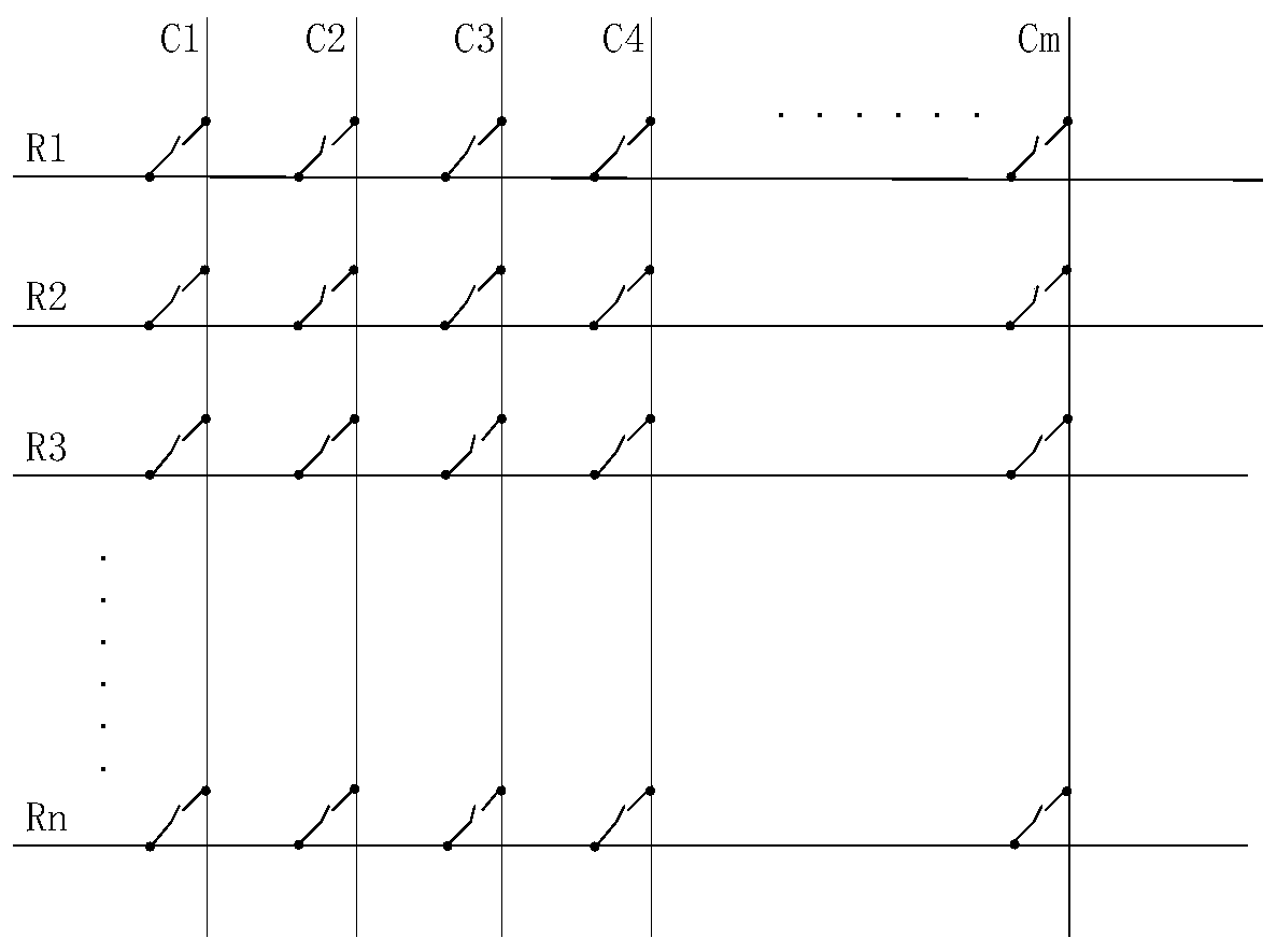
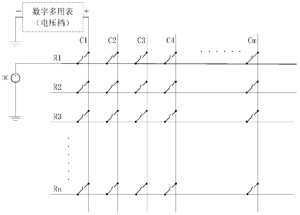
[0029] combine Figure 4 , a matrix switch relay fault detection device, including a circuit board 1, the circuit board is provided with a connector 2, a first port A and a second port B, and all signal input terminals and all signal output terminals of the matrix switch are connected to On the connector 2, all signal input terminals of the matrix switch connected to the connector 2 are connected to the first port A, and all signal output terminals of the matrix switch connected to the connector 2 are connected to a resistor The other ends of the resistors are connected to the second port B, and a digital multimeter is connected between the first port and the second port.

Embodiment 2

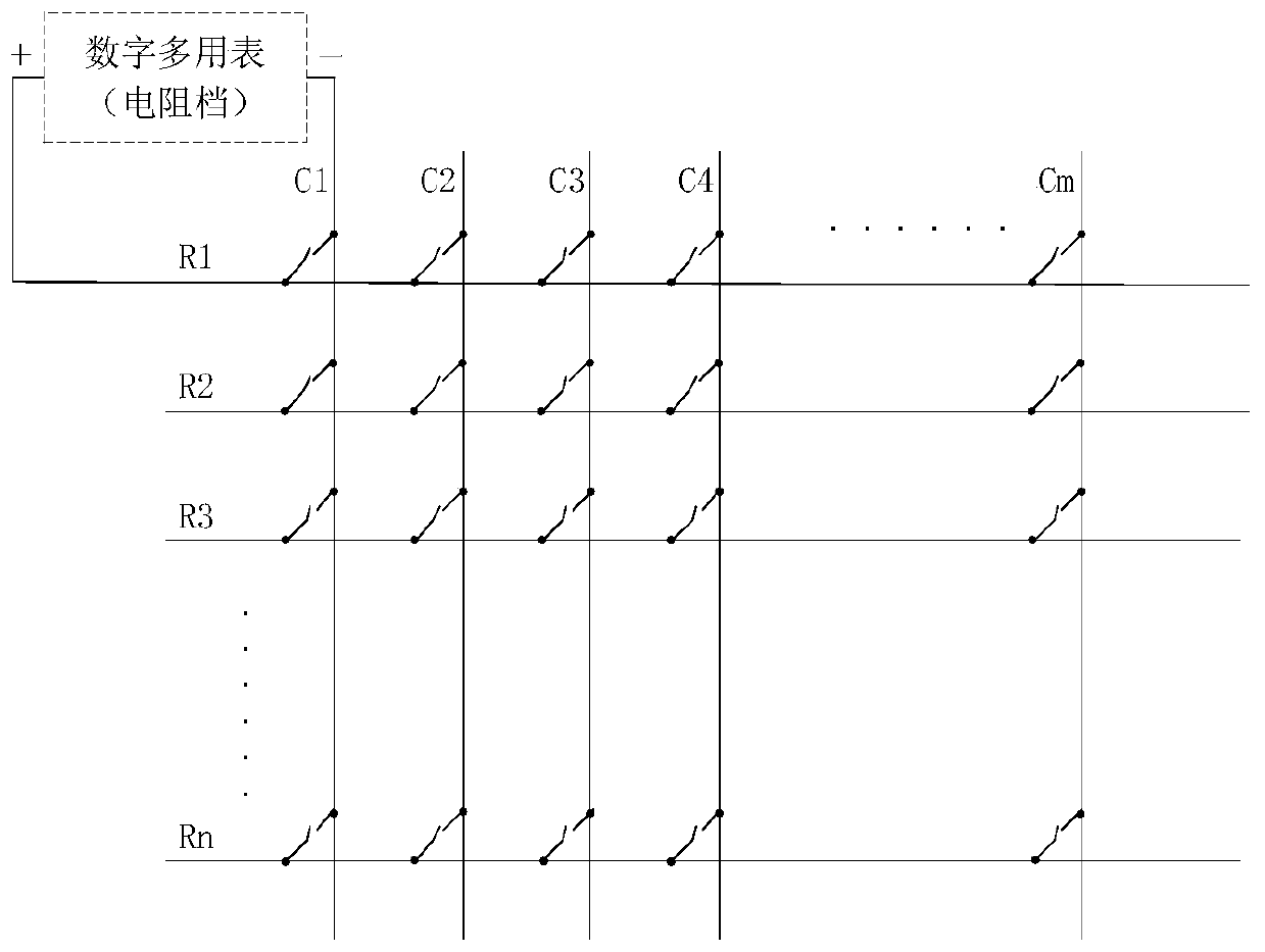
[0031] The detection method of a kind of matrix switch relay failure detection device of above-mentioned embodiment 1, wherein, the matrix switch is the single line matrix switch of n*m mode, n is the number of rows, m is the number of columns, and the resistance value of each resistor is x, The value of x is relatively large, and x is from 100 kohms to 10 megohms. The value of x can be changed according to actual operation requirements, and is not necessarily limited to the above range.

[0032] The detection method comprises the following steps:

[0033] Step 1: Close the relays connected to the signal input terminals in the first row of the matrix switch and the signal output terminals in the m columns, and disconnect the relays in the remaining rows, and use a digital multimeter to measure the resistance between the first port A and the second port B , since all resistors are connected in parallel, the theoretical resistance between the first port and the second port shoul...

Embodiment 3

[0045] Take a 32*128 mode single-line matrix switch as an example, the resistance value is x;

[0046] Such as Figure 4 As shown, the detection steps include:

[0047] Step 1: Close the relays connected to the signal input terminals of the first row of the matrix switch and the 128 signal output terminals, and disconnect the relays of the remaining rows. Use a digital multimeter to measure the resistance between the first port A and the second port B. Since all resistors are connected in parallel, the theoretical resistance between the first port and the second port should be x / 128, compare the resistance measured by the digital multimeter with the x / 128 value;

[0048] Step 2: Repeat step 1 to test the resistance value of the 32 rows of the matrix switch, and compare the resistance value measured by the digital multimeter of each row with the x / 128 value;

[0049] Step 3: If the resistance value of this line measured by the digital multimeter is the same as the x / 128 value...


PUM


Abstract

The invention provides a matrix switch relay failure detection device and detection method. By adding a circuit board, a resistor with the same resistance value is connected in series with each signal output channel of the matrix switch, and the resistance value of the parallel resistance is measured for multiple switch channels. According to The change of the measured value judges whether there is a fault in the switching relay. The present invention does not need to close and disconnect all matrix switch relays sequentially, and adopts the level-by-level average grouping method to measure the resistance value of multi-way switches with relay faults, and narrows the detection range step by step, which can greatly shorten the fault detection time and improve the detection efficiency , especially for large-scale matrix switches.

Description

technical field [0001] The invention relates to the field of matrix switch relay fault detection, in particular to a matrix switch relay fault detection device and detection method. Background technique [0002] The matrix switch is an important part of the automatic test system (ATS). Its main function is to realize the flexible switching of signals from the ATS test resources to the unit under test (UUT), and it is the key to realize the design of the automatic test interface. The structure of the matrix switch is cross-arranged in rows and columns, each node is a relay, connecting a row and column, each node can be operated independently, and signal routing can be realized by setting different combinations of nodes, such as figure 1 shown. The matrix switch is the center of signal transmission in ATS, and its reliability is particularly important in ATS. The discharge phenomenon that occurs when the relay is turned on and off can cause contact erosion and reduce the life...

Claims


Application Information

Patent Timeline
Patent Type & Authority Patents(China)
IPC IPC(8): G01R31/327
CPCG01R31/3278
Inventor 邹芳宁张海庆李振风牛玉礼刘硕夏磊郭荣斌
Owner THE 41ST INST OF CHINA ELECTRONICS TECH GRP
Why Eureka
Try Eureka