A Method of Suppressing Commutation Torque Ripple of Brushless DC Motor

A brushed DC motor, phase torque technology, applied in the direction of torque ripple control, electronic commutator, etc., can solve the problem of the delay of the Hall sensor detection position signal, the inconsistency of the turn-off phase current falling rate and the on-phase current rising rate, problems such as advance, to achieve the effect of suppressing commutation torque ripple, improving operating efficiency, and being easy to implement

Active Publication Date: 2019-08-06
HARBIN ENG UNIV
View PDF5 Cites 0 Cited by
  • Summary
  • Abstract
  • Description
  • Claims
  • Application Information

AI Technical Summary

Problems solved by technology

[0003] Due to the inductance in the motor winding, during commutation, the off-phase current drop rate is inconsistent with the on-phase current rise rate, causing commutation torque ripple, which limits the application of brushless DC motors in high-precision and low-noise fields
[0004] On the other hand, the ideal installation interval of the Hall sensor is 120° electrical angle. However, due to slight errors in the mechanical installation process, the signal detected by the Hall sensor is delayed or advanced, which affects the stable operation of the motor.

Method used


Image

  • A Method of Suppressing Commutation Torque Ripple of Brushless DC Motor
  • A Method of Suppressing Commutation Torque Ripple of Brushless DC Motor
  • A Method of Suppressing Commutation Torque Ripple of Brushless DC Motor

Examples


Embodiment

[0100] The specifications of the brushless DC motor used in the present invention are shown in Table 2:

[0101] Table 2. Motor Specifications and Parameters

[0102]

[0103] When the motor is running in the rated state, convert the parameters in the table to obtain the mechanical angular velocity of the motor Ω=50π(rad / s), the electrical angular velocity of the motor ω=200π(rad / s), the amplitude of the back electromotive force E=92.7V, and the phase current stable value I 0 =22A, electromagnetic torque T in steady state e = 26 Nm.

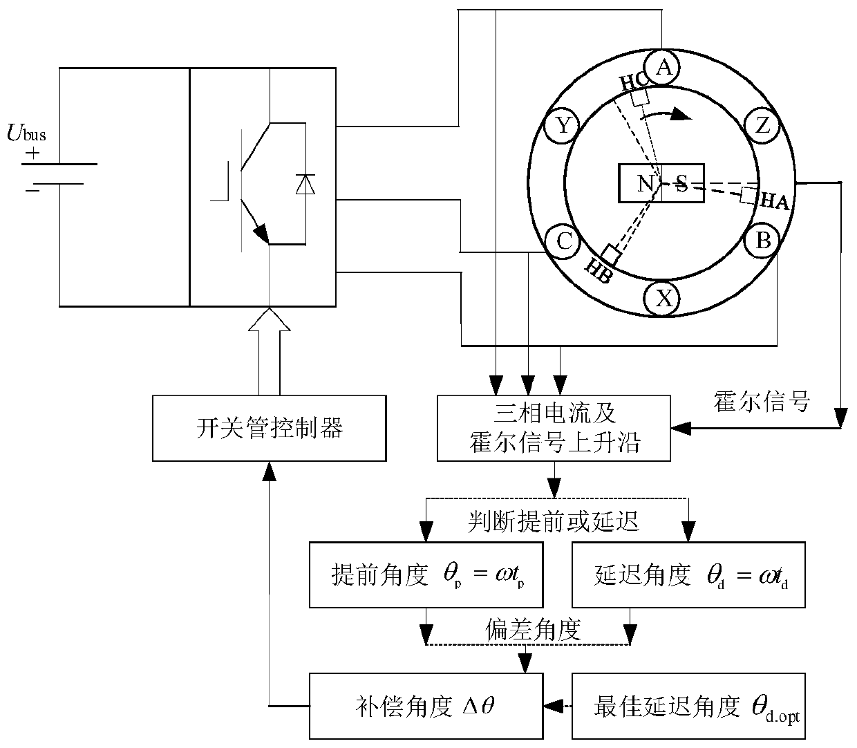
[0104] Substituting the parameters into formula (5) (3) to obtain the duty cycle D during the delay period d and off-phase current I 1 With delay angle θ d change curve, such as Figure 10 shown, the duty cycle D d If the delay is less than 1 within the 30° electrical angle range, the PWM duty cycle can be adjusted to ensure that the motor torque is constant during the delay; Figure 11 As shown, the turn-off phase current I 1 One-to-...


PUM


Abstract

The invention relates to a method capable of automatically compensating Hall deviation for suppressing commutation torque pulse of a brushless DC motor. The method comprises the steps of detecting a rising edge transient switch-off phase current of a Hall signal, comparing the transient switch-off phase current with a phase current stable value, placing in a delayed way when the transient switch-off phase current is larger than the stable value, otherwise placing in advance; detecting the rising edge transient switch-off phase current of the Hall signal, and acquiring a delay angle Theta<d> according to an expression of the switch-off phase current and delay time t<d>; detecting a time interval of the switch-off phase current reduced to 0 from a stable value, and acquiring an advance degree Theta according to an expression of the time interval and advance time; making time of the switch-off phase current reduced to 0 consistent with time of a conduction phase current raised to the stable value so as to acquire an optimal delay angel Theta<d.opt>; deducting the optimal delay angle from a deviation angle to obtain a compensation angle, and performing compensation within a next electrical period. By the method, the commutation torque pulse is suppressed as well as the Hall installation deviation is compensated, the running efficiency of the motor is improved, and the method is simple and is easy to implement.

Description

technical field [0001] The invention relates to the control field of a brushless direct current motor, in particular to a method for suppressing commutation torque ripple of a brushless direct current motor which can automatically compensate Hall deviation. Background technique [0002] Brushless DC motor is a DC motor with electronic commutation instead of mechanical commutation. It maintains the excellent characteristics of DC motor, has good starting and speed regulation characteristics, and has the advantages of simple structure, wide speed range and high power density. , which are widely used in aerospace, electric locomotives, home appliances, and industrial automation systems. [0003] Due to the presence of inductance in the motor windings, during commutation, the off-phase current drop rate is inconsistent with the on-phase current rise rate, causing commutation torque ripple, which limits the application of brushless DC motors in high-precision and low-noise fields...

Claims


Application Information

Patent Timeline
Patent Type & Authority Patents(China)
IPC IPC(8): H02P6/10H02P6/16
CPCH02P6/10H02P6/16
Inventor 姚绪梁江晓明张燕赵继成林浩鲁光绪王峰常英健曹叶鸣孙小琴
Owner HARBIN ENG UNIV
Why Eureka
Try Eureka