An intelligent vehicle-blocking roadblock system

A roadblock and vehicle blocking technology, which is applied in the field of intelligent vehicle blocking system, can solve the problems of low safety, limited field of view, slow response speed of the vehicle blocking system, etc., and achieve the effect of improving the reaction speed

Active Publication Date: 2019-07-09
BEIJING ZHUOAOSHIPENG TECH CO LTD
View PDF5 Cites 0 Cited by
  • Summary
  • Abstract
  • Description
  • Claims
  • Application Information

AI Technical Summary

Problems solved by technology

[0003] In order to facilitate people's identification at night, the existing hydraulic lifting roadblocks are equipped with LED lights for night lighting, so power is needed. Usually, a buried ground wire is used to provide power for the LED lights, and the buried ground wire has many inconveniences.
[0004] The response speed of the existing vehicle blocking system is slow, and the operating system of the lifting barrier is installed in the guard box at the entrance. When the operator finds an illegal vehicle and then operates the lifting barrier to rise, the time has already missed 1-2 seconds, and it is likely not to be able to Effective interception of vehicles; low safety, due to the limited field of vision of the operator or when there is a misoperation, the lifting barrier will rise. If there are vehicles and pedestrians near the lifting barrier, safety accidents will easily occur

Method used


Image

  • An intelligent vehicle-blocking roadblock system
  • An intelligent vehicle-blocking roadblock system
  • An intelligent vehicle-blocking roadblock system

Examples


Embodiment

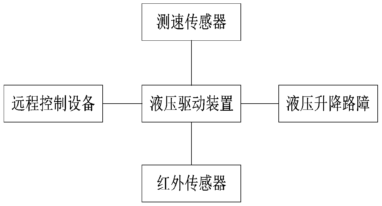
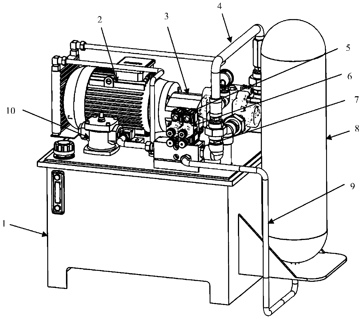
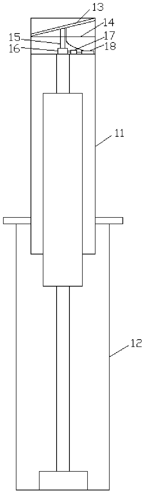
[0036] Such as Figure 1 ~ Figure 4 As shown, an intelligent vehicle blocking roadblock system provided by an embodiment of the present invention includes: a speed measuring sensor, a remote control device, a hydraulic drive device, a hydraulic lifting roadblock and an infrared sensor arranged in the lifting roadblock;

[0037] The speed measuring sensor is used to detect the speed of the incoming vehicle, and send the incoming vehicle speed to the hydraulic drive device;

[0038] The infrared sensor is used to detect whether there is an obstacle near the lifting barrier, and send the detection result to the hydraulic drive device;

[0039] The remote control device is used to send the received control command to the hydraulic drive device;

[0040] The hydraulic drive device is used to judge whether to control the operation of the hydraulic lifting roadblock according to the detection result, and to control the driving flow rate of the hydraulic oil according to the speed of...


PUM


Abstract

The invention belongs to the technical field of roadblock equipment, and discloses an intelligent vehicle stopping roadblock system. The intelligent vehicle stopping roadblock system comprises a speed detecting sensor, an infrared sensor, a remote controlling device, a hydraulic driving device and a hydraulic lifting roadblock, wherein the speed detecting sensor is used for detecting the speed of a vehicle; the infrared sensor is used for detecting if barrier exists nearby a lifting roadblock; the remote controlling device is used for sending the received controlling instruction to the hydraulic driving device; the hydraulic driving device is used for determining whether the hydraulic lifting roadblock is controlled to work or not according to the detected result, controlling a driving flow velocity of a hydraulic oil according to a vehicle-coming speed, and then driving the lifting of the hydraulic lifting roadblock; and the hydraulic lifting roadblock is used for lifting quickly or slowly according to driving of the hydraulic driving device. According to the intelligent vehicle stopping roadblock system, the lifting of the hydraulic lifting roadblock is automatically controlled according to the speed detected by the speed detecting sensor, the reaction speed of the system is improved, and the lifting speed of the hydraulic lifting roadblock is controlled according to the detected velocity magnitude, meanwhile, detecting of the infrared sensor plays a safety protection role, and it is guaranteed that the vehicle and pedestrian cannot be accidently injured during rising of the roadblock.

Description

technical field [0001] The invention relates to the technical field of roadblock equipment, in particular to an intelligent vehicle-blocking roadblock system. Background technique [0002] Existing vehicle blocking roadblock system is made up of lifting roadblock, drive system, control system, operating switch. When an illegal vehicle punches the card, the operator sends an instruction to the control system by pressing the button of the operation switch, and then the control system controls the drive system, and finally the drive system provides power to lift and lower the roadblock to achieve the purpose of intercepting the vehicle. [0003] In order to facilitate people's identification at night, existing hydraulic lift roadblocks are equipped with LED lights for night lighting, so power is needed. Usually, the buried ground wires are used to provide power for the LED lights, and the buried ground wires have many inconveniences. [0004] The response speed of the existing...

Claims


Application Information

Patent Timeline
Patent Type & Authority Patents(China)
IPC IPC(8): E01F13/04
CPCE01F13/046
Inventor 刘镭周鹏杜玉娟
Owner BEIJING ZHUOAOSHIPENG TECH CO LTD
Why Eureka
Try Eureka