Method and system for boost control

A technology for boosting engine and exhaust pressure, which is applied in electrical control, charging system, engine control, etc., and can solve problems such as increased delta pressure at both ends of the engine, damage to turbocharger hardware, and increased expansion ratio

Active Publication Date: 2021-12-03
FORD GLOBAL TECH LLC
View PDF11 Cites 0 Cited by
  • Summary
  • Abstract
  • Description
  • Claims
  • Application Information

AI Technical Summary

Problems solved by technology

During this period, high exhaust manifold pressure and exhaust pressure peaks lead to increased delta pressure across the engine, which increases engine pump work, which can adversely affect engine efficiency, performance, emissions, and fuel economy
Also, during this time, the expansion ratio of the turbine may increase excessively, which may cause damage to the turbocharger hardware
Additionally, such exhaust pressure peaks and high expansion ratios can lead to high cycle fatigue and ultimately degradation of several engine components such as seals, gaskets, exhaust valves and cylinder components

Method used


Image

  • Method and system for boost control
  • Method and system for boost control
  • Method and system for boost control

Examples


Embodiment Construction

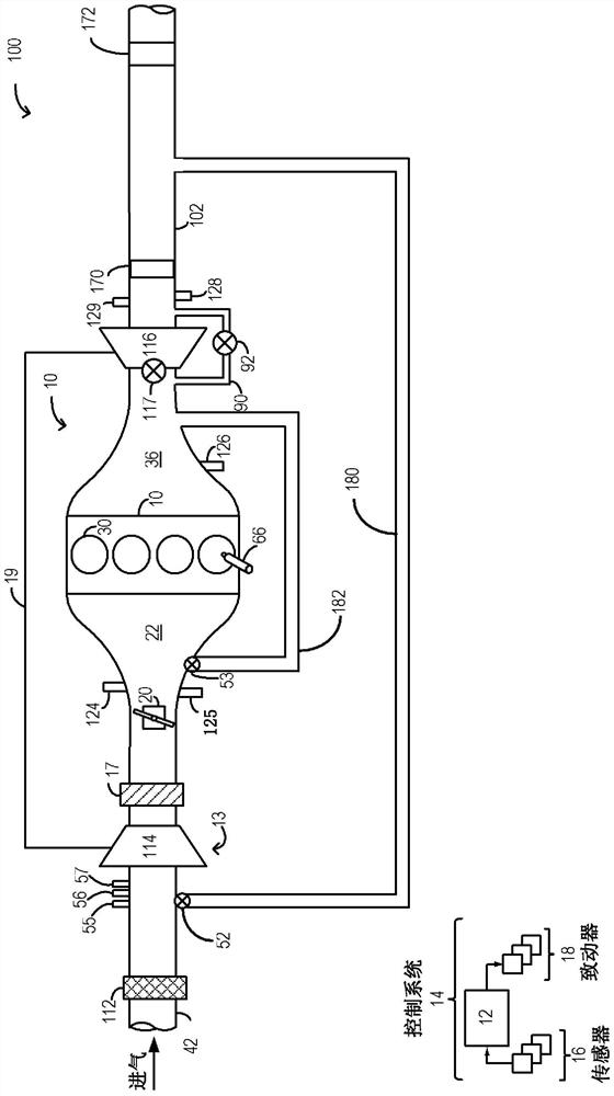
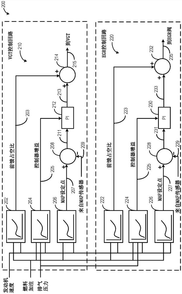
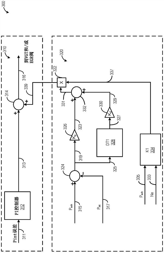
[0014] The following description relates to systems and methods for pressure control in boosted engine systems. figure 1 An example engine boosting system including a variable geometry turbine (VGT) and exhaust gas recirculation (EGR) system is shown. The opening of the VGT and EGR valves can be feedback-controlled by the engine controller based on multiple input signals including intake and exhaust manifold pressures, engine speed, and fueling schedule, such as figure 2 is shown in the example control system of . In addition to PI controllers (proportional-integral controllers), such as image 3 As shown, a gain-scheduled PD (proportional-derivative) controller can be used to further adjust the VGT vane position based on engine speed, exhaust manifold pressure, and the difference between exhaust and intake manifold pressure (△ pressure) At least one of , wastegate valve position and EGR valve opening. The engine controller can be configured to execute control programs suc...


PUM


Abstract

The present application discloses methods and systems for boost control. Methods and systems are provided for pressure control in boosted engine systems. Adjust variable geometry turbine (VGT) geometry and / or wastegate (WG) and / or Exhaust gas recirculation (EGR) valve opening in order to reduce the difference between exhaust manifold pressure and intake manifold pressure, thereby reducing pumping air work losses.

Description

technical field [0001] The description generally relates to methods and systems for pressure control in boosted engine systems. Background technique [0002] Engine systems may be configured with a boosting device, such as a turbocharger or supercharger, to provide a charge of charge air and improve peak power output, fuel economy, and emissions. A turbocharger may have a variable geometry turbine (VGT), in which the impeller vanes (or vanes) of the turbine are adjusted to vary boost pressure and exhaust pressure. The position of the VGT's impeller vanes may vary based on factors including engine speed, torque demand, desired response time, fuel economy, intake and exhaust manifold pressures, and emissions requirements. VGT tuning achieves reduced pumping losses by changing the aspect ratio of the turbocharger. [0003] One example method for adjusting VGT geometry is shown in Buckland et al. US 6,672,060. In it, the VGT geometry is adjusted by a feedback control loop tha...

Claims


Application Information

Patent Timeline
Patent Type & Authority Patents(China)
IPC IPC(8): F02D43/00F02D41/14F02B37/12F02M26/06
CPCF02B37/12F02D41/0007F02D41/0052F02D41/1401F02D2200/04F02D2200/101F02D2041/1409F02D41/18F02D2041/141F02D2041/1422F02D2200/0406F02B37/183F02B37/24F02D41/1448Y02T10/12Y02T10/40F02M26/02F02M26/52F02B37/18F02D23/00F02D41/021F02D41/1402F02D41/1444
Inventor M·J·汉德三世T·A·布鲁贝克M·J·V·尼乌斯塔特B·L·福尔顿
Owner FORD GLOBAL TECH LLC
Why Eureka
Try Eureka