

System and method for warming exhaust device of engine exhaust system
An engine system and engine technology, applied in the direction of exhaust devices, engine components, combustion engines, etc., can solve the problems of high exhaust temperature, difficult to achieve, low exhaust temperature, etc., and achieve the effect of reducing emissions
- Summary
- Abstract
- Description
- Claims
- Application Information
AI Technical Summary
Problems solved by technology
Method used
Image

Examples
Embodiment Construction
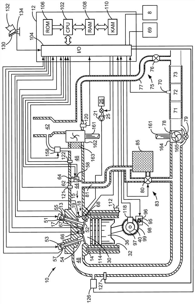
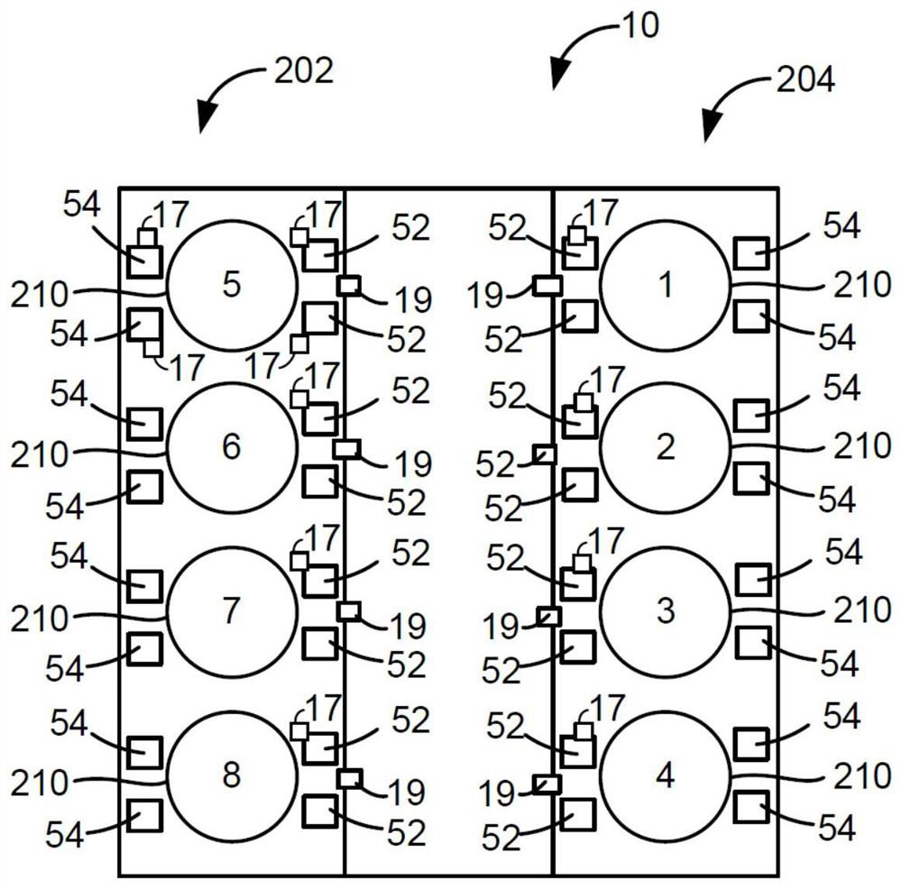
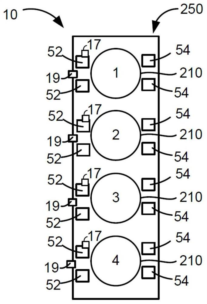
[0012] This specification relates to the operation of a diesel engine including an exhaust aftertreatment device. The engine can be Figure 1 to Figure 2B type shown in . The engine can be as image 3 and Figure 4 The operations shown in the sequence. Figure 1 to Figure 2B The engine can be based on Figure 5 and Figure 6 method of operation to increase exhaust temperature and reduce engine fuel consumption.
[0013] refer to figure 1 , an internal combustion engine 10 (comprising a plurality of cylinders, figure 1 One of the cylinders shown in ) is controlled by the electronic engine controller 12 . Controller 12 from figure 1 The various sensors receive signals and adopt figure 1 The various actuators are used to adjust engine operation based on the signals received and instructions stored on the controller's memory.
[0014] Engine 10 includes combustion chamber 30 and cylinder walls 32 with piston 36 positioned therein and connected to crankshaft 40 . The cy...
PUM
 Abstract
Description
Claims
Application Information