
Steel pipe concrete combined column

A technology of steel pipe concrete and composite columns, applied in the direction of columns, pier columns, pillars, etc., can solve the problems of poor fire performance of steel pipes, reduced structural performance, and reduced structural performance, so as to improve fire performance, compensate for structural performance loss, and prevent heat The effect of direct contact with the steel pipe

Active Publication Date: 2017-10-10
殷诗宝 +1
View PDF6 Cites 3 Cited by
  • Summary
  • Abstract
  • Description
  • Claims
  • Application Information

AI Technical Summary

Problems solved by technology

[0003] In view of the problems in the existing concrete-filled steel pipe structure that the concrete is separated from the steel pipe after solidification, resulting in a decrease in structural performance, and the poor fire performance of the exposed steel pipe, the applicant provides a structurally reasonable composite steel pipe concrete column, which can effectively prevent the concrete from being separated from the steel pipe after solidification. The steel pipe peels off to reduce the structural performance, and at the same time, it can improve the fire performance of the composite column

Method used


Image

  • Steel pipe concrete combined column
  • Steel pipe concrete combined column

Examples


Embodiment Construction

[0021] The specific implementation manner of the present invention will be described below in conjunction with the accompanying drawings.

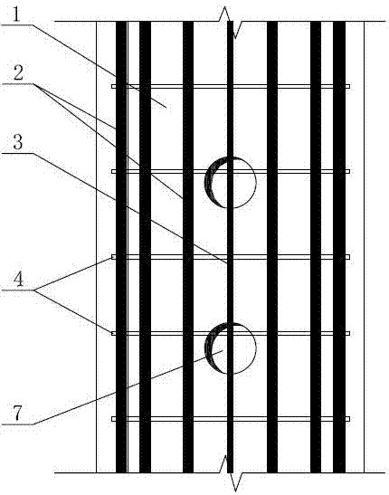
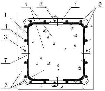
[0022] Such as figure 1 with figure 2 As shown, the steel pipe 1 of the present invention is a square or rectangular steel pipe, and the walls of the steel pipe 1 are processed with holes 7 at intervals. round. A plurality of reinforcing bars 2 and a structural reinforcing bar 3 are installed on each side of the steel pipe 1 along the longitudinal direction, the reinforcing bars 2 are intermittently welded to the outer wall of the steel pipe 1, and the structural reinforcing bars 3 are located at the positions of the holes 7. Ring-shaped stirrups 4 are provided at intervals on the outer circumference of the steel pipe 1 , and the stirrups 4 are tied or welded to the reinforcing steel bars 2 and the structural steel bars 3 . The two ends of the tie bars 5 are provided with hooks, which are respectively hooked on the structural steel bar...


PUM


Abstract

The invention discloses a steel pipe concrete combined column. Holes are machined in the wall face of a steel pipe, reinforcing steel bars and constructional steel bars are mounted on the exterior of the steel pipe in the longitudinal direction, and meanwhile reinforcement stirrups are arranged on the periphery of the steel pipe at intervals. The reinforcement stirrups are connected with the reinforcing steel bars and the constructional steel bars in a bound or welded mode. Hooks are arranged at the two ends of tie bars, and the tie bars are hooked on the constructional steel bars of the outer sides of the holes after penetrating through the two corresponding opposite holes correspondingly. The tie bars are connected with the constructional steel bars in a bound or welded mode, and concrete is poured on the interior and the outer wall of the steel pipe. The concrete inside the steel pipe can communicate with the concrete outside the steel pipe through the holes in the side wall of the steel pipe, and meanwhile the tie bars can also fix the concrete, so that the phenomenon that the steel pipe is separated from the concrete due to shrinkage of the concrete in the steel pipe is effectively prevented, and the work performance of the combined column is ensured. The reinforcing steel bars and the reinforcement stirrups are longitudinally and transversely staggered to form a framework of the concrete of the outer wall of the steel pipe so as to fix the concrete to the outer wall of the steel pipe. The concrete of the outer wall has the heat insulation effect, thus the phenomenon that heat makes direct contact with the steel pipe can be effectively prevented, and the fireproof performance of the whole combined column is improved.

Description

technical field [0001] The invention relates to the field of building structures, in particular to a steel pipe concrete composite column which avoids the separation of concrete and steel pipes and improves fire resistance. Background technique [0002] With the rapid development of my country's urban construction and the advancement of construction industrialization, the demand for high-rise buildings and large-scale factory buildings is increasing. However, due to the shortcomings of traditional reinforced concrete structures such as poor seismic performance, it is difficult to realize the diversification of functions of high-rise buildings under the conditions of large loads and large spans, let alone important indicators such as land saving and energy saving required by the development direction of the construction industry. It has not adapted to the needs of the development of high-rise buildings. The steel pipe concrete structure is formed by filling the steel pipe wi...

Claims


Application Information

Patent Timeline
Patent Type & Authority Applications(China)
IPC IPC(8): E04C3/36E04B1/94
CPCE04B1/94E04C3/36
Inventor 殷诗宝
Owner 殷诗宝
Learn More