Variable-diameter autorotation farm irrigation spraying head
A farmland irrigation and self-rotation technology, applied in the field of agricultural irrigation, can solve the problems of low service life of sprinklers, difficult control of sprinkler irrigation range and sprinkler irrigation water volume, etc., and achieve the effect of even sprinkler irrigation
- Summary
- Abstract
- Description
- Claims
- Application Information
AI Technical Summary
Problems solved by technology
Method used
Image
Examples
specific Embodiment approach 1
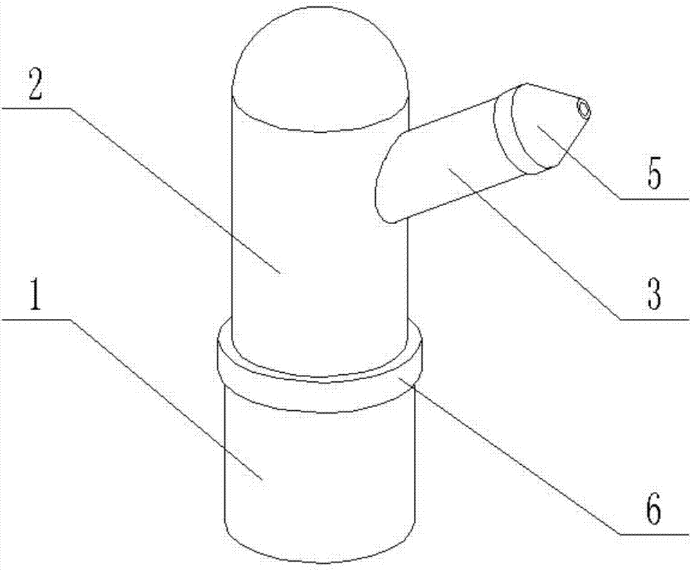
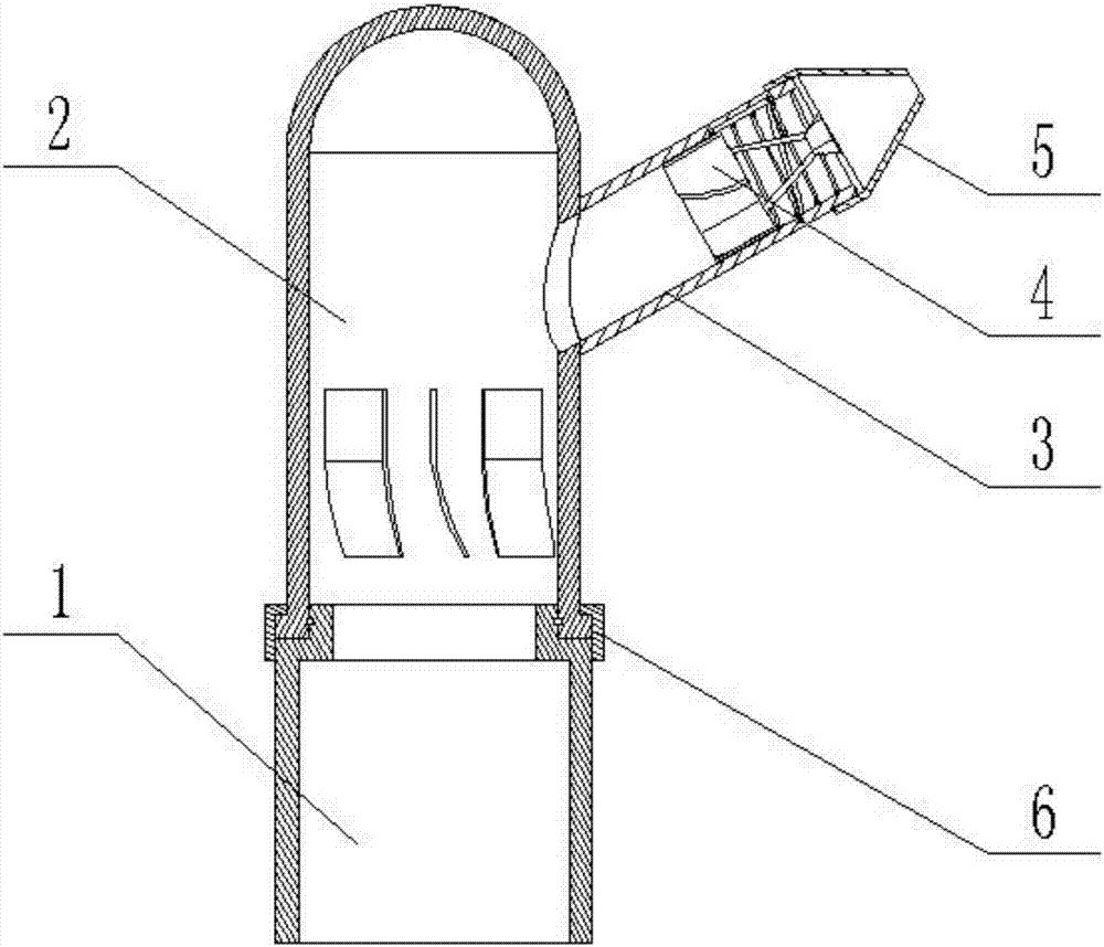
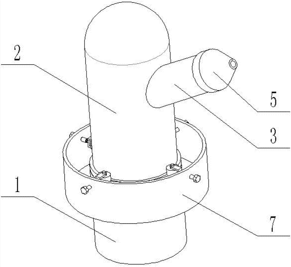
[0048] Combine below Figure 1-15Describe this embodiment, a self-rotating farmland irrigation nozzle with variable diameter, including a nozzle base 1, a rotating pipe 2, a nozzle pipe 3, a diameter reducing device 4, a nozzle 5 and a connecting piece 6, and the nozzle base 1 includes a bottom pipe 1 -1 and the socket head 1-2, the upper end of the bottom pipe 1-1 is welded and connected to the socket head 1-2, and the outer diameter of the socket head 1-2 is smaller than the outer diameter of the bottom pipe 1-1;
[0049] The rotating tube 2 includes a rotating tube body 2-1, an annular boss 2-2, a water outlet hole 2-3 and a plurality of rotating blades 2-4. The rotating tube body 2-1 is a cylindrical structure with an open lower end and a hollow interior. The lower end of the rotating tube body 2-1 is welded to the annular boss 2-2, the upper end of the side wall of the rotating tube body 2-1 is provided with a water outlet hole 2-3, and the middle end of the inner side wa...
specific Embodiment approach 2
[0055] Combine below Figure 1-15 Describe this embodiment, this embodiment will further explain the first embodiment, the outer side of the socket head 1-2 is provided with a sealing ring insertion groove I1-2-1, and the lower end of the inner wall of the rotating pipe body 2-1 is provided with Sealing ring inlay groove Ⅱ2-1-1, ring inlay groove Ⅰ1-2-1 is set opposite to ring inlay groove Ⅱ2-1-1, ring inlay groove Ⅰ1-2-1 is snapped into ring inlay groove Ⅱ2-1-1 There is a rubber sealing ring to ensure the sealing between the nozzle base 1 and the rotating tube 2 at one time, and the rubber sealing ring will not hinder the relative rotation between the nozzle base 1 and the rotating tube 2.
specific Embodiment approach 3
[0056] Combine below Figure 1-15 This embodiment will be described. This embodiment will further describe the first embodiment. The inserting sleeve 4-1 and a plurality of blades 4-2 constitute an impeller mechanism, and the rotation direction of the impeller mechanism is the same as that of the spiral chute 3-1. Similarly, when the blade 4-2 is subjected to the action of the water flow to rotate the diameter reducing device 4, the insertion column 4-5 can slide along the spiral chute 3-1.
PUM
 Abstract
Description
Claims
Application Information
 - R&D
- Intellectual Property
- Life Sciences
- Materials
- Tech Scout
- Unparalleled Data Quality
- Higher Quality Content
- 60% Fewer Hallucinations
Browse by: Latest US Patents, China's latest patents, Technical Efficacy Thesaurus, Application Domain, Technology Topic, Popular Technical Reports.
© 2025 PatSnap. All rights reserved.Legal|Privacy policy|Modern Slavery Act Transparency Statement|Sitemap|About US| Contact US: help@patsnap.com


