A tank washing machine with magnetic drive

A technology of magnetic drive and tank washing machine, which is applied to the cleaning equipment of ship liquid tanks, motor vehicles, ships, etc., and can solve problems such as wear, reduced equipment reliability, and equipment failure

Active Publication Date: 2016-04-13
ZHEJIANG UNIV +1
View PDF5 Cites 0 Cited by
  • Summary
  • Abstract
  • Description
  • Claims
  • Application Information

AI Technical Summary

Problems solved by technology

[0003] The existing tank washing machine equipment generally uses high-pressure working medium to drive the built-in rotating mechanism (turbine or runner) to obtain the power required for nozzle rotation, and then realize the automatic operation of the tank washing machine through this power; most tank washing machines The improvement is either aimed at the nozzle structure, or setting a deflector at the inlet to increase the driving force of the impeller, or adjusting the control mechanism for the nozzle, but the power transmission in them is all carried out by means of mechanical transmission, and the high-pressure medium is used in the cleaning machine. When flowing, the inevitable problem of mechanical transmission is the sealing problem. Poor sealing will cause the impurities in the working medium to wear the mechanical transmission parts, cause equipment failure, and reduce the reliability of the equipment.
In addition, the nozzle angle adjustment of most tank washing machines is to achieve 360° rotation in the plane, and there are many cleaning dead angles, which have a great impact on various tank washing processes and cleaning effects.

Method used


Image

  • A tank washing machine with magnetic drive
  • A tank washing machine with magnetic drive
  • A tank washing machine with magnetic drive

Examples


Embodiment 1

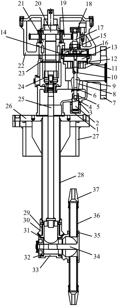
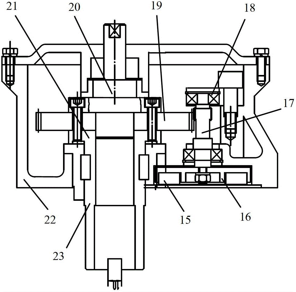
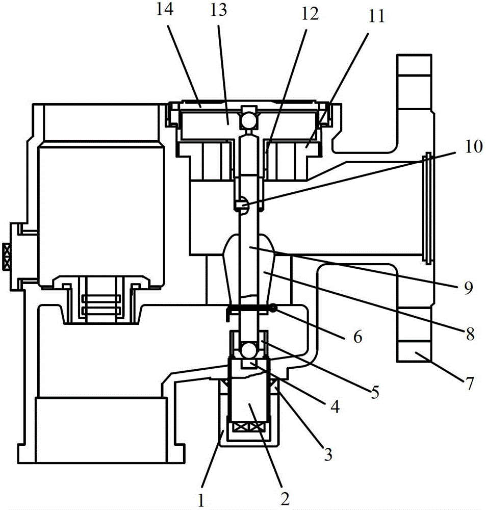
[0025] Embodiment 1, figure 1 A tank washing machine with magnetic drive is given, which consists of a reduction box ( figure 2 shown), power box ( image 3 shown) and body ( Figure 4 and Figure 5 shown) composition.

[0026] The power box includes a protective cover 1, a screw rod 2, a lock nut 3, a thrust block 4, a bearing 5, a hole pin 6, a power box body 7, a runner 8, a runner shaft 9, a connecting pin 10, a bearing sleeve 11, a shaft Cover 12, disk 13 and isolation cover 14; as image 3 As shown, the power box body 7 is provided with a power box cavity and a power box water inlet cavity, and the power box cavity and the power box water inlet cavity are connected to each other through a conical passage, and a water inlet is provided on the power box cavity; A runner shaft 9 is arranged in the cavity of the power box, and the upper end of the runner shaft 9 is fixed to the magnetic disk 13 through a connecting pin 10 (the magnetic disk 13 is made of magnetic mater...


PUM


Abstract

The invention discloses a magnetic transmission tank washing machine which comprises a gearbox, a power control box and a machine body, wherein the gearbox, the power control box and the machine body are sequentially connected from top to bottom. The power control box comprises a power control box body, a power control box cavity and a power control box water inlet cavity are formed in the power control box body, the power control box cavity and the power control box water inlet cavity are communicated with each other, a water inlet is formed in the power control box cavity, a rotary wheel axle is arranged in the power control box cavity, and a rotary wheel and a magnetic disk are arranged on the rotary wheel axle. The gearbox comprises a main shaft, and a magnet corresponding to the magnetic disk is arranged in the gearbox, arranged in a magnetic coupling device in a sleeved mode, and connected with the main shaft after meshing of multi-stage gears. The machine body comprises a main pipe, a machine body water inlet cavity is formed in the main pipe, a transmission shaft is arranged in the machine body water inlet cavity, the main shaft penetrates through the power control box water inlet cavity and then is connected with the transmission shaft, a water spray system is arranged at the lower end of the transmission shaft, and the power control box cavity is communicated with the machine body water inlet cavity.

Description

technical field [0001] The invention relates to a cleaning device, in particular to an oil tank cleaning device for various oil tankers in the shipbuilding industry, which uses crude oil or seawater as the cleaning medium, that is, a tank cleaning machine with magnetic drive. Background technique [0002] During oil tanker transportation, heavy components such as paraffin and asphalt in crude oil will continuously precipitate out of crude oil to form a thick layer of oil residue sediment. If the oil is not removed after unloading, after several voyages, the accumulation of oil residue will hinder the normal unloading of the oil tanker, and even greatly reduce the oil carrying capacity of the oil tanker. For the oil residue of oil tankers, the oil tank is generally cleaned by using the jet flow generated by the high-pressure fluid (0.4~1.2MPa) through the nozzle by using the tank washing machine. The amount of seawater discharged to the refinery and the need for manual clean...

Claims


Application Information

Patent Timeline
Patent Type & Authority Patents(China)
IPC IPC(8): B63B57/02
Inventor 杨帅付国涛叶素丹吴大转
Owner ZHEJIANG UNIV
Why Eureka
Try Eureka