Rotation valve and assembly thereof

A technology of rotary valves and components, applied in valve details, multi-way valves, valve devices, etc., can solve the problems of increasing equipment processing consumables, reducing equipment work efficiency, inconvenient automatic control, etc., to reduce manufacturing costs and equipment space occupancy , Reduce production consumables, reduce production costs

Pending Publication Date: 2017-10-13
CHENGDU SEPMEM SCI & TECH
View PDF8 Cites 0 Cited by
  • Summary
  • Abstract
  • Description
  • Claims
  • Application Information

AI Technical Summary

Problems solved by technology

[0003] However, the current complex control pipelines and control valves are not only inconvenient to realize automatic control, but also increase the processing consumables of the equipment and reduce the working efficiency of the equipment due to the large number of valves.

Method used


Image

  • Rotation valve and assembly thereof
  • Rotation valve and assembly thereof
  • Rotation valve and assembly thereof

Examples


no. 1 example

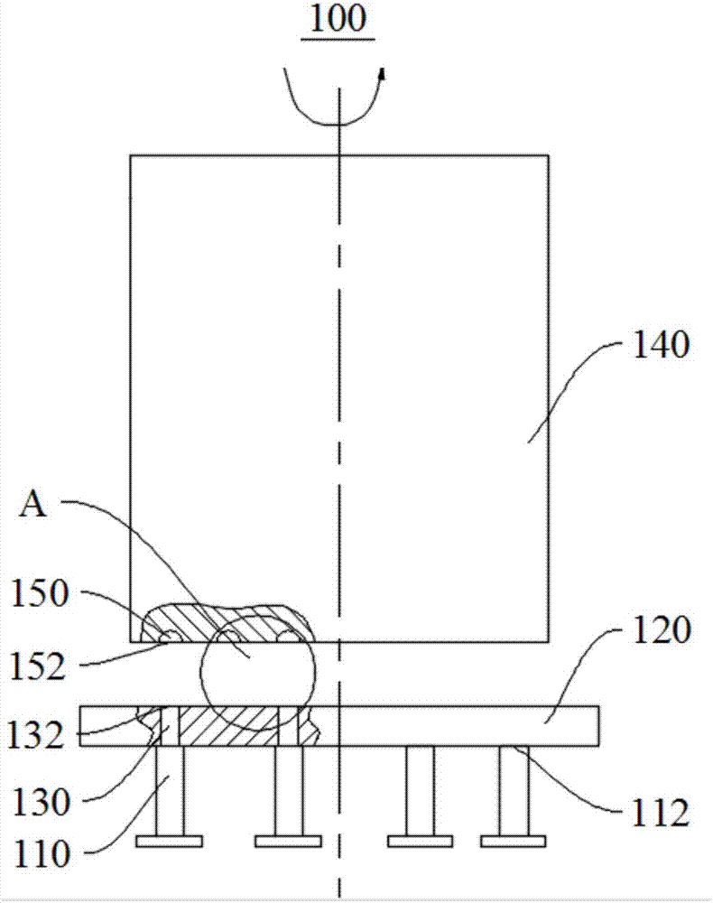
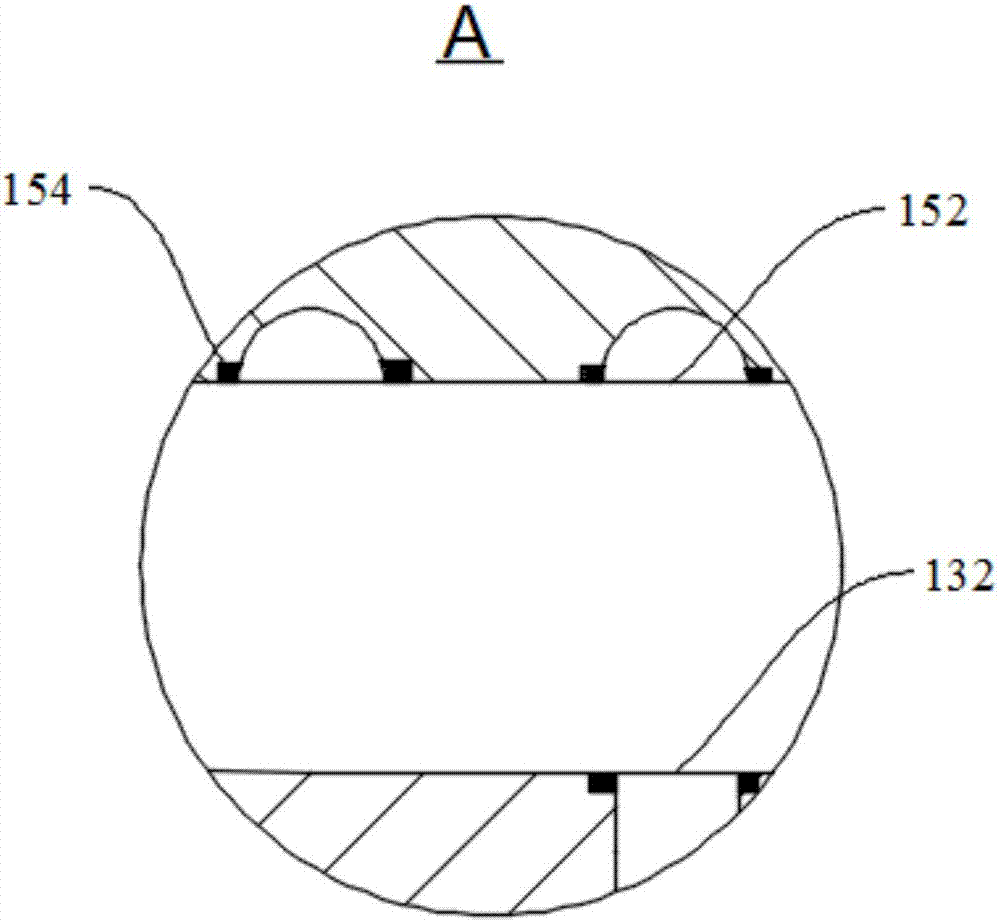
[0031] Please refer to figure 1 , this embodiment provides a rotary valve 100, which is mainly used for multi-pipeline control in chemical production. The rotary valve 100 includes a non-rotating part 120 and a rotating part 140, wherein the two opposite end faces of the non-rotating part 120 and the rotating part 140 cooperate with each other, and the rotating part 140 is rotated by itself, by virtue of the contact between the end faces of the non-rotating part 120 The mating relationship controls the state of communication between the plurality of external conduits 110 connected to the non-rotating member 120 .

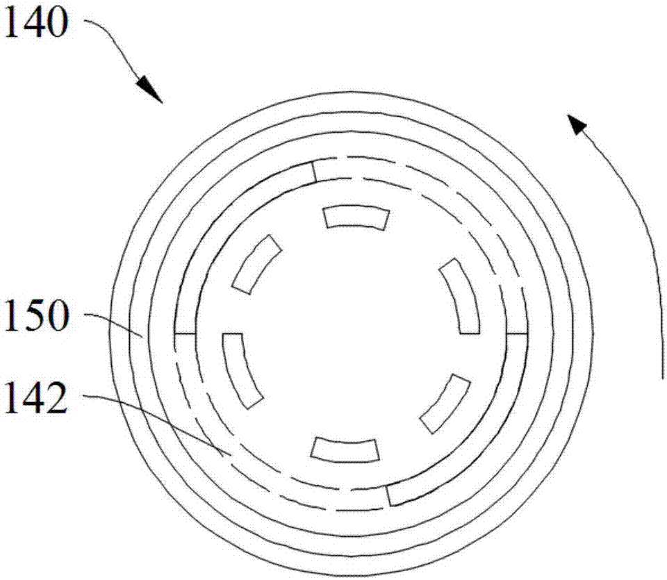
[0032] Further, the non-rotating part 120 is provided with a plurality of first flow channels 130 communicating with the external pipeline 110, the rotating part 140 is provided with a plurality of second flow channels 150 matched with the plurality of first flow channels 130, and the plurality of first flow channels 150 A communication pipe network is formed betwe...

no. 2 example

[0045] Please refer to Figure 5 , the present embodiment provides a rotary valve assembly 20, which is substantially the same as the rotary valve assembly 10 provided in the first embodiment, the difference is that the rotary valve assembly 10 of this embodiment also includes a control for controlling the rotary drive device 260 System 270.

[0046] Further, in order to improve the working efficiency and automation level of the rotary valve assembly 20 , this embodiment provides that the rotary valve assembly 20 includes a control system 270 . Specifically, the control system 270 includes a controller and a program editor communicatively connected with the controller, wherein the controller is electrically connected with the motor 262 of the rotary driving device 260 . It should be noted that the controller can not only control the rotation rhythm of the rotating part 240, but also control the rotation speed, and through the program editor, the regulation of the operation of...


PUM


Abstract

The invention discloses a rotation valve and an assembly thereof, and relates to the field of valves. The rotation valve is used for enabling a non-rotation part to fit to the end surface of a rotation part, so that a plurality of first runners arranged on the non-rotation part are in sealing fit to a plurality of second runners arranged on the rotation part to form a communication pipe network, and therefore, switching of each pipeline in the communication pipe network is controlled by controlling rotation of the rotation part; and a rotation drive device which is matched with a rotation valve and a control system are arranged, so that automatic operation of a rotation valve assembly is realized, and working efficiency of the rotation valve is greatly improved. According to the rotation valve and the assembly comprising the rotation valve disclosed by the invention, manufacturing cost of multi-pipeline equipment and an equipment space occupation rate can be reduced; and moreover, efficient switching control on multiple pipelines also can be realized, and very high working efficiency is realized, and therefore, the rotation valve and the assembly thereof have very important popularization and application values.

Description

technical field [0001] The invention relates to the field of valves, in particular to a rotary valve and components thereof. Background technique [0002] Many chemical production processes involve multi-pipeline control, such as gas pressure swing adsorption or gas temperature swing adsorption, which involve multiple pipelines and multiple control valves. [0003] However, the current complex control pipelines and control valves are not only inconvenient to realize automatic control, but also increase the processing consumables of the equipment and reduce the working efficiency of the equipment due to the large number of valves. Contents of the invention [0004] The object of the present invention is to provide a rotary valve, which has low processing cost, low operating failure rate, and high working efficiency for complex multi-pipeline control in chemical production. [0005] Another object of the present invention is to provide a rotary valve assembly, which include...

Claims


Application Information

Patent Timeline
Patent Type & Authority Applications(China)
IPC IPC(8): F16K11/074F16K31/04F16K27/04
CPCF16K11/074F16K27/045F16K31/04
Inventor 张惊涛宋强
Owner CHENGDU SEPMEM SCI & TECH
Why Eureka
Try Eureka