
Dustproof camera

A camera and dust-proof technology, which is applied in the field of cameras, can solve the problems that the camera is easy to accumulate dust and affect the shooting effect, and achieve a variety of effects to increase the effect

Active Publication Date: 2017-10-13
重庆万建电子工程有限责任公司
View PDF6 Cites 12 Cited by
  • Summary
  • Abstract
  • Description
  • Claims
  • Application Information

AI Technical Summary

Problems solved by technology

[0004] Aiming at the deficiencies in the prior art, the purpose of the present invention is to provide a dust-proof camera to solve the problem in the prior art that the lens of the camera is easy to accumulate dust and affect the shooting effect

Method used


Image

  • Dustproof camera
  • Dustproof camera
  • Dustproof camera

Examples


Embodiment

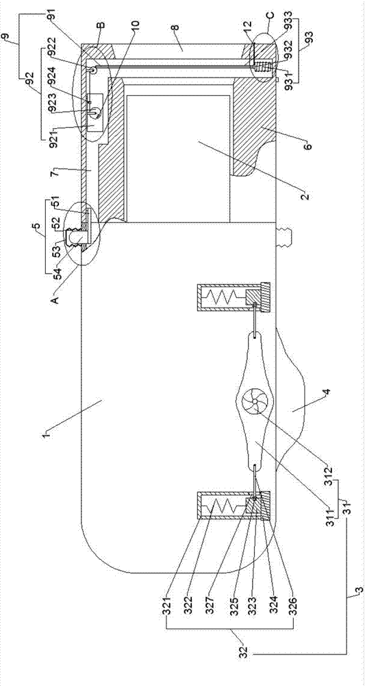
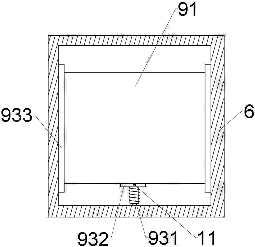
[0019] refer to Figure 1 to Figure 7 Shown: a dust-proof camera, including a body 1, a lens 2 is detachably connected to the body 1, a buffer device 3 is arranged on the body 1, and a square protective shell 6 is connected to the body 1 through a clamping mechanism 5 , the lens 2 is arranged in the protective shell 6, a cavity 7 is opened in a side wall of the protective shell 6, a through hole 8 matching the size of the lens 2 is opened at the end of the protective shell 6, and the protective shell 6 is provided with a A dustproof device 9 for dustproofing the lens 2.

[0020] The buffer device 3 includes a drive mechanism 31 and two buffer mechanisms 32 that are symmetrically arranged with the drive mechanism 31 as a symmetrical axis and have the same structure; The position is the middle part of the cam 311, and the cam 311 is strip-shaped, and the width of the middle part of the cam 311 is large, and the width of both ends is small, and the middle part is smoothly transi...


PUM


Abstract

The invention discloses a dustproof camera comprising a camera body and a lens. A square protective shell is connected on the camera body through a clamping mechanism. The lens is arranged in the protective shell. The protective shell is provided with a through hole, and the protective shell is internally provided with a dustproof device. The dustproof device comprises a transparent dustproof tape, a cleaning mechanism and a traction mechanism. The side wall of the protective shell is internally provided with a cavity. The cleaning mechanism is arranged in the cavity. The cleaning mechanism comprises a liquid storage tank and a steering wheel. A winding roller is rotatably arranged in the liquid storage tank. The dustproof tape is tensioned between the winding roller and the steering wheel, and a cleaning member is arranged between the steering wheel and the winding roller. The traction mechanism comprises an electrified solenoid and an adsorption block. The internal side wall of the protective shell is provided with oppositely arranged slide slots. The dustproof tape is slidably clamped in the slide slots. Compared with the cameras in the prior art, the dustproof effect of the lens can be realized and use is convenient.

Description

technical field [0001] The invention relates to the field of cameras, in particular to a dustproof camera. Background technique [0002] A camera converts an optical image signal into an electrical signal for storage or transmission. When we shoot an object, the light reflected on the object is collected by the camera lens to focus on the light-receiving surface of the imaging device (such as the target surface of the imaging tube), and then the light is converted into electrical energy through the imaging device, which is obtained "Video Signal". The photoelectric signal is very weak and needs to be amplified by a pre-amplification circuit, and then processed and adjusted by various circuits. The final standard signal can be sent to a recording medium such as a video recorder for recording, or transmitted through a communication system or sent to a monitor. display. [0003] At present, the camera is widely used. After a long time of use, the camera will more or less acc...

Claims


Application Information

Patent Timeline
Patent Type & Authority Applications(China)
IPC IPC(8): H04N5/225B08B17/04B08B1/02
CPCB08B17/04H04N23/50H04N23/51B08B1/20B08B1/12
Inventor 岳军刘春莲汪洋徐守中
Owner 重庆万建电子工程有限责任公司
Learn More