Exhaust gas treatment device and exhaust gas treatment method

An exhaust gas treatment device and exhaust gas treatment technology, applied in chemical instruments and methods, separation methods, separation of dispersed particles, etc., can solve problems such as air pollution

Inactive Publication Date: 2017-10-13
JFEENG CORP
View PDF5 Cites 8 Cited by
  • Summary
  • Abstract
  • Description
  • Claims
  • Application Information

AI Technical Summary

Problems solved by technology

[0002] Exhaust from cement kilns, non-ferrous metal smelting furnaces or mercury-containing wastes after incineration in waste incin

Method used


Image

  • Exhaust gas treatment device and exhaust gas treatment method
  • Exhaust gas treatment device and exhaust gas treatment method
  • Exhaust gas treatment device and exhaust gas treatment method

Examples


no. 1 approach >

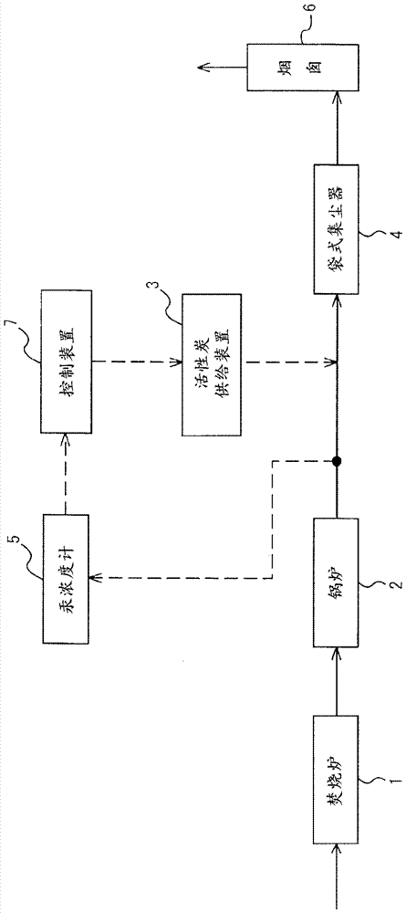
[0067] In showing the schematic structure of the device of this embodiment figure 1 Among them, in the exhaust flow path that guides the exhaust gas from the incinerator 1 to the chimney 6, the boiler 2 and the bag dust collector 4 as a dust collecting device are arranged from the upstream side. The upstream position blows into the exhaust gas flow path the activated carbon supply device 3 for adsorbing and removing mercury in the exhaust gas and the control device 7 for controlling it, and a bag filter is also installed on the downstream side of the bag filter 4, that is, a bag filter. The outlet of the dust collector 4 or the chimney 6 measures the mercury concentration meter 5 in the exhaust gas, and the above-mentioned mercury concentration meter 5 is connected to the control device 7 so that the measured value of the mercury concentration meter 5 is sent to the above-mentioned control device as an output signal. device7.

[0068] In the apparatus of the present embodimen...

no. 2 approach >

[0073] figure 2 Compared with the above-described first embodiment, the present embodiment shown is only different in the arrangement position of the mercury concentration meter 5 , and the others are the same. therefore, figure 2 in, for with figure 1 The parts that are common to those of the first embodiment are given the same symbols, and description thereof will be omitted.

[0074] In this embodiment, if figure 2 As seen in , the mercury concentration meter 5 is arranged to measure the mercury concentration in the exhaust gas at the following positions: the downstream side of the incinerator 1 and the upstream side of the bag filter 4, and the upstream side of the activated carbon injection position of the activated carbon supply device 3 s position. In the present embodiment, the control device 7 grasps the relationship between the mercury concentration at the measurement position, the activated carbon supply amount, and the mercury concentration at the downstream...

no. 3 approach >

[0077] image 3 Compared with the above-mentioned second embodiment, the present embodiment shown has, in addition to the first mercury concentration meter 5A arranged on the upstream side of the position where the activated carbon is blown into the activated carbon supply device 3, a bag dust collector is also provided. The downstream side of the bag filter 4, that is, the outlet of the bag filter 4 or the second mercury concentration meter 5B for measuring the mercury concentration in the exhaust gas by the chimney 6, and the measured value of the second mercury concentration meter 5B is sent to the control device 7 as an output signal . Except for this point, it is the same as the second embodiment. therefore, image 3 in, for with figure 2 The parts that are common to the parts of the second embodiment are assigned the same symbols, and the description thereof will be omitted.

[0078] In this embodiment, if image 3 It can be seen that, in addition to the first merc...


PUM


Abstract

The problem addressed by the present invention is to provide an exhaust gas treatment device and method for reliable absorption and removal of mercury in exhaust gas from a furnace, and for providing activated carbon thereto in a suitable activated carbon quantity even if the mercury concentration in the exhaust gas varies. Provided is an exhaust gas treatment device that has a dust collection device 4, which carries out dust elimination treatment on the exhaust gas that contains mercury from a furnace 1, provided in a position downstream from the furnace 1 and is provided with an activated carbon supply device 3 for blowing activated carbon into an exhaust gas flow path wherein exhaust gas is guided from the furnace 1 to the dust collection device 4, wherein the exhaust gas treatment device has a mercury concentration gauge 5, which measures mercury concentration in the exhaust gas, provided on the downstream side of the dust collection device 4 and is provided with a control device 7 which maintains and controls the activated carbon supply amount to a prescribed minimum value such that the mercury concentration in the exhaust gas on the downstream side of the dust collection device 4 is a setting value or less on the basis of a value measured by the mercury concentration gauge 5.

Description

technical field [0001] The present invention relates to a processing device and method for treating mercury-containing exhaust gas discharged from various factories such as waste incineration facilities, cement manufacturing plants, thermal power plants, and non-ferrous metal smelting plants. Background technique [0002] Exhaust gas from cement kilns, non-ferrous metal smelting furnaces or mercury-containing wastes incinerated in waste incinerators sometimes contains mercury. If it is released directly into the atmosphere, it will cause air pollution and become question. Accordingly, it is desirable to remove mercury from exhaust gases. [0003] In addition, the "Minamata Treaty on Mercury" was adopted in 2013, and actions to strengthen mercury management worldwide are underway. After the entry into force of the treaty, measures to suppress mercury emissions from facilities subject to mercury emission restrictions are under study. Examples of facilities subject to mercur...

Claims


Application Information

Patent Timeline
IPC IPC(8): B01D53/64B01D53/83
CPCB01D53/64B01D53/83
Inventor 长尾厚志平山敦三浦崇臼井祐人
Owner JFEENG CORP
Why Eureka
Try Eureka