Low creep bearing and method for installing in supercharger

A supercharger and bearing technology, applied in the direction of shaft installation, bearing assembly, pumping device components for elastic fluid, etc., can solve the problem of not providing damping capacity, shear force resistance, etc.

Inactive Publication Date: 2017-10-13
EATON CORP
View PDF6 Cites 4 Cited by
  • Summary
  • Abstract
  • Description
  • Claims
  • Application Information

AI Technical Summary

Problems solved by technology

These low viscosity lubricants can fill some of the space, but they do not provide effective damping capability or resistance to shear forces

Method used


Image

  • Low creep bearing and method for installing in supercharger
  • Low creep bearing and method for installing in supercharger
  • Low creep bearing and method for installing in supercharger

Examples


Embodiment Construction

[0019] Reference will now be made in detail to the examples illustrated in the accompanying drawings. Wherever possible, the same reference numbers will be used throughout the drawings to refer to the same or like parts. Directional references such as "left" and "right" are for ease of reference to the drawings.

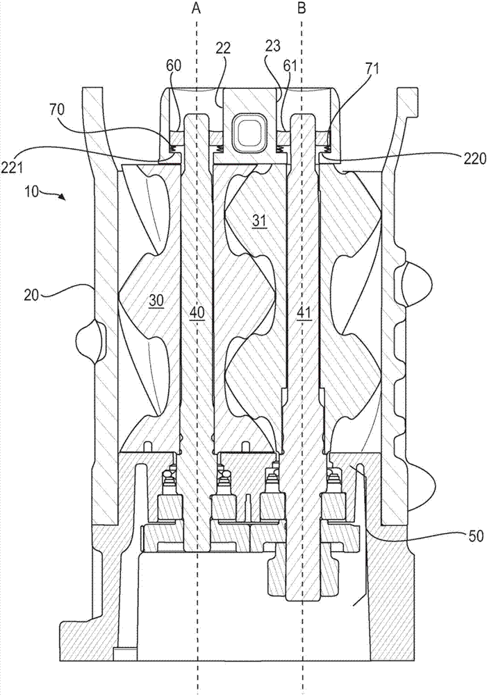
[0020] 1 shows an example of a supercharger assembly 10 including rotors 30, 31 in a housing 20. The shaft 40, 41 is positioned along the axis A, B in the center of the rotor 30, 31. The shafts 40, 41 fit into the shaft bores 22, 23 at one end of the axes A, B and fit into the transfer case 50 at the other end of the axes A, B.

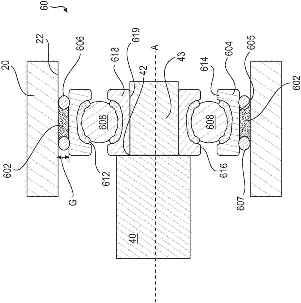
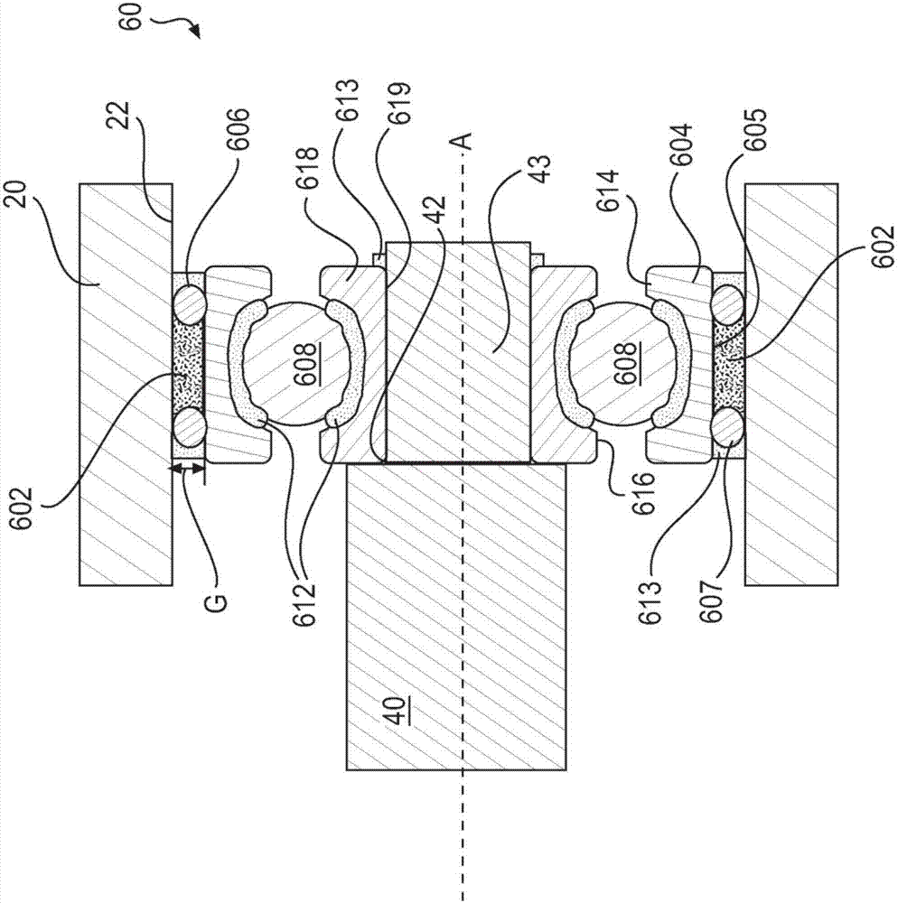
[0021] The shafts 40 , 41 fit into bearings 60 , 61 , all of which are located in the shaft bores 22 , 23 . One can fit the shaft 40 , 41 into the bearing 60 , 61 before or after placing the shaft 40 , 41 in the shaft hole 22 , 23 . For example, one may first fit the first bearing 60 onto the first shaft 40 and then slip fit the first sh...


PUM


Abstract

A supercharger assembly comprises a housing, a shaft bore in the housing, a shaft extending into the shaft bore, wherein the shaft comprises an axis, and a bearing assembly located between the shaft bore and the shaft. The bearing assembly comprises an outer ring. The outer ring comprises an outer face. A grease is located between the outer face of the outer ring and the shaft bore. The grease has a viscosity greater than International Standards Organization Viscosity Grade 100.

Description

technical field [0001] The present application relates to damping technology in a supercharger and provides a bearing mount for damping rotor shaft motion in a supercharger. Background technique [0002] Root style or twin rotor superchargers are subject to chatter when the rotating lobes engage. Vibration displaces the rotor shaft in the supercharger housing. Prior art bearings creep in the housing due to chatter and displacement. [0003] Tolerance stacking can contribute to this chatter, causing vibrations during operation because, for example, there is spacing between components in the bearings, between the bearings and the shaft, and between the bearings and the housing of the supercharger. These spaces may expand and contract due to thermal expansion caused by both changes in operating temperature and changes in ambient temperature. [0004] Vibration can also cause the rotor in a Roots-style supercharger to "travel", that is, to move in the axial direction. Travel...

Claims


Application Information

Patent Timeline
Patent Type & Authority Applications(China)
IPC IPC(8): F16C33/66F16C35/077
CPCF16C33/6633F16C35/077F16C2360/24F16C2226/12F16C2210/04F02B33/38F02B39/14F16C2360/43F01C21/02F04C29/021F04C18/123F04C2240/50F16C19/06F16C27/045Y02T10/12
Inventor 贾森·布雷迪
Owner EATON CORP
Why Eureka
Try Eureka