
Speed reducer or speed increaser

一种增速装置、冠齿轮的技术,应用在卷扬装置、传动装置、齿轮传动装置等方向,能够解决无法增大减速比增速比、齿数差等问题,达到提高旋转刚性、提高效率、增大直径的效果

Active Publication Date: 2017-10-13
THK CO LTD
View PDF11 Cites 1 Cited by
  • Summary
  • Abstract
  • Description
  • Claims
  • Application Information

AI Technical Summary

Problems solved by technology

However, there is a limit to the difference in the number of teeth of the two spur gears, and there is a problem that the reduction ratio or the increase ratio cannot be increased.

Method used


Image

  • Speed reducer or speed increaser
  • Speed reducer or speed increaser
  • Speed reducer or speed increaser

Examples


Embodiment Construction

[0044]Hereinafter, a reduction gear transmission according to an embodiment of the present invention will be described in detail with reference to the drawings. However, the reduction gear transmission of the present invention can be embodied in various forms, and is not limited to the embodiments described in this specification. This embodiment is provided so that those skilled in the art can fully understand the scope of the invention through sufficient disclosure of the specification.

[0045]

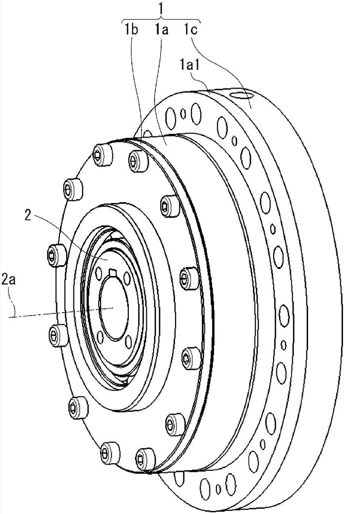
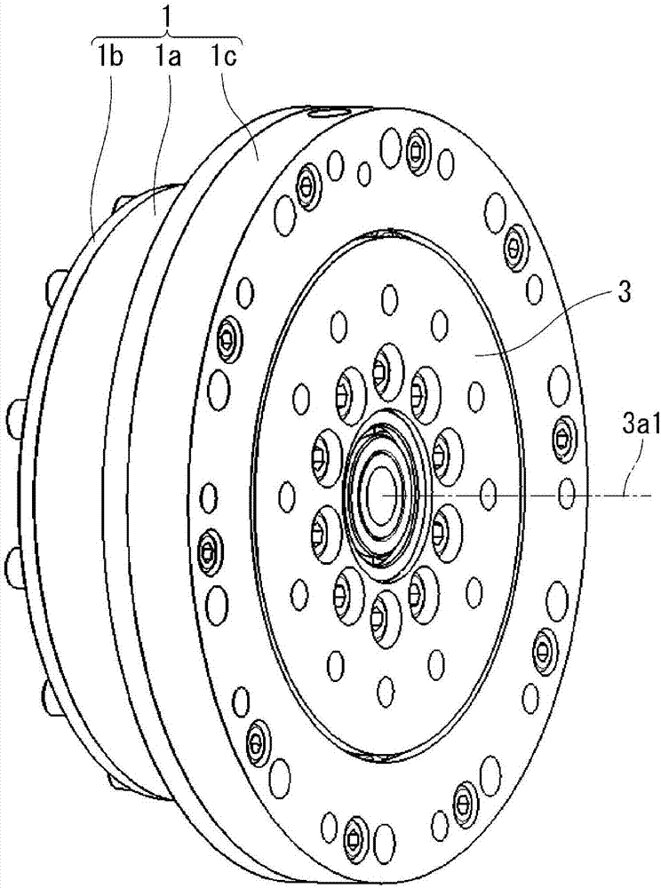
[0046] figure 1 A perspective view showing the appearance of the input shaft side of the reduction gear transmission according to the first embodiment of the present invention, figure 2 A perspective view showing the appearance of the output unit side of the reduction gear transmission. It should be noted that the same reference numerals are assigned to the same structures in the drawings and the following description.

[0047] An input shaft 2 and an output unit 3 are rotatab...


PUM


Abstract

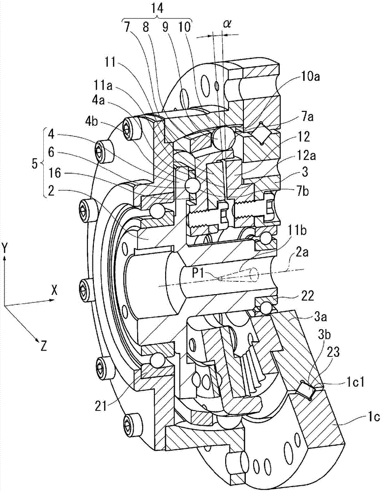
[Problem] To provide a speed reducer or speed increaser for which rotational stiffness can be increased. [Solution] This speed reducer or speed increaser comprises: a housing 1; a first crown gear 11; a support 14 that is disposed outside of the first crown gear 11 in the radial direction and supports the first crown gear 11 so that undulating motion is allowed but rotation is not allowed with respect to the housing 1; a second crown gear 12 that can rotate with respect to the housing 1, has a different number of teeth than the first crown gear 11, and faces the first crown gear 11; and a cam 5 that causes the first crown gear 11 to be inclined with respect to the second crown gear 12 so that the first crown gear 11 meshes with the second crown gear 12 and causes the first crown gear 11 to undulate so that the meshing location is moved.

Description

technical field [0001] The present invention relates to a deceleration or speed-up device. The deceleration or speed-up device makes a first crown gear and a second crown gear having different numbers of teeth face each other, tilts the first crown gear relative to the second crown gear so that the first The crown gear is meshed with the second crown gear, and the first crown gear is caused to wave motion to move the meshing portion. Background technique [0002] As a conventional speed reduction or speed reduction device, a speed reduction or speed reduction device obtained by meshing two spur gears having an involute tooth profile is known. Since it is easy to manufacture and has excellent efficiency, spur gears with an involute tooth profile are mostly used in deceleration or speed-up devices. However, there is a limit to the difference in the number of teeth of the two spur gears, and there is a problem that it is impossible to increase the reduction ratio or the increa...

Claims


Application Information

Patent Timeline
Patent Type & Authority Applications(China)
IPC IPC(8): F16H1/32F16D3/20F16H53/02F16H55/08F16H55/17
CPCF16H55/08F16H1/321F16H53/02
Inventor 齐藤秀生水谷雄一
Owner THK CO LTD
Learn More