a cooling device

An equipment and abutment technology, which is applied in the field of cooling equipment, can solve the problems of poor mixing effect of cold water and normal temperature water, unhealthy health of workshop workers, and fixed orientation of toppings, and achieves wide spraying range and convenient spraying orientation. , the effect of improving work efficiency

Inactive Publication Date: 2018-06-26
江苏金孔雀面业有限公司
View PDF4 Cites 0 Cited by
  • Summary
  • Abstract
  • Description
  • Claims
  • Application Information

AI Technical Summary

Problems solved by technology

[0002] Summer is coming, the weather is hot, factories, workshops and other places emit a lot of heat due to long-term mechanical operation, resulting in high indoor temperature, which is extremely unfavorable to the health of workshop workers, and can easily lead to heat stroke
These places generally do not install air conditioners, but use simple fans and sprinkle water on the ground and the air to achieve the purpose of cooling. The existing sprinkler cooling measures rely on manual watering or using leather pipes to pour water, which is time-consuming and laborious. Some special sprinklers The device can add ice water or ice cubes to the water to efficiently realize the cooling function, but the mixing effect of the internal cold water and normal temperature water is poor, and the pouring head is fixed and does not move, and the sprinkling range is small

Method used


Image

  • a cooling device
  • a cooling device
  • a cooling device

Examples


Embodiment Construction

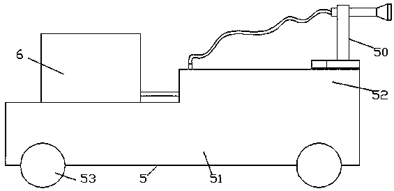
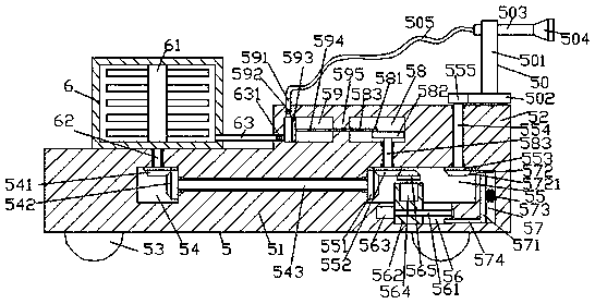
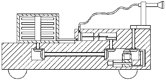
[0021] Such as Figure 1-Figure 4As shown, a cooling device of the present invention includes a vehicle platform 5 composed of a first base platform 51 and a second base platform 52, and the second base platform 52 is located on the top right side of the first base platform 51, so A storage box 6 is provided at the top left side of the first base 51, a sprinkler 50 is connected to the top right side of the second base 52, a stirring device 61 is connected inside the storage box 6, and the storage box 6 6 The first base 51 below the bottom is provided with a first inner cavity 54, and the first inner cavity 54 is connected with a first adapter shaft 62 extending up and down on the inner top surface. The extension section at the top of the connecting shaft 62 passes through the bottom of the storage box 6 and is fixedly connected with the stirring device 61 , the extension section at the bottom of the first connecting shaft 62 penetrates into the first inner cavity 54 and the en...


PUM


Abstract

The invention discloses cooling equipment which comprises a vehicle platform composed of a first base platform and a second base platform. The second base platform is located on the top of the right side of the first base platform; a storage box is arranged on the top of the left side of the first base platform; a water spraying device is connected on the top of the right side of the second base platform in a switch-over mode; a stirring device is connected in the storage box in a switch-over mode; a first inner cavity is formed in the position, on the lower portion of the bottom of the storage box, of the first base platform; a first switch-over connecting shaft extending up and down is connected inside the top surface inside the first inner cavity in a switch-over mode; the top extending section of the first switch-over connecting shaft penetrates through the bottom of the storage box and is fixedly connected with the stirring device; the bottom extending section of the first switch-over connecting shaft extends into the first inner cavity, and the tail end of the bottom extending section of the first switch-over connecting shaft is fixedly provided with a first cone pulley; and a second inner cavity which is formed in the right side of the first inner cavity is formed in the position, on the lower portion of the second base platform, of the first base platform. The cooling equipment is simple in structure and convenient to operate, the time and labor are saved, the spraying direction is easy to adjust, operation stability is high, and the water spraying range is wide.

Description

technical field [0001] The invention relates to the technical field of cooling, in particular to a cooling device Background technique [0002] Summer is coming, the weather is hot, factories, workshops and other places emit a lot of heat due to long-term mechanical operation, resulting in high indoor temperature, which is extremely unfavorable to the health of workshop workers, and can easily lead to heat stroke. These places generally do not install air conditioners, but use simple fans and sprinkle water on the ground and the air to achieve the purpose of cooling. The existing sprinkler cooling measures rely on manual watering or using leather pipes to pour water, which is time-consuming and laborious. Some special sprinklers The device can add ice water or ice cubes to the water to efficiently realize the cooling function, but the mixing effect of the internal cold water and normal temperature water is poor, and the pouring head is fixed and does not move, and the sprink...

Claims


Application Information

Patent Timeline
Patent Type & Authority Patents(China)
IPC IPC(8): F24F5/00F24F11/89F24F13/02
CPCF24F5/0035F24F13/0218F24F2221/125
Inventor 沈科丹
Owner 江苏金孔雀面业有限公司
Why Eureka
Try Eureka