Motor vehicle door lock

A motor vehicle door lock, motor vehicle technology, applied in electric vehicle locks, electric locks, vehicle locks, etc., to achieve the effect of simple structure

Active Publication Date: 2017-10-17
KIEKERT AG
View PDF5 Cites 2 Cited by
  • Summary
  • Abstract
  • Description
  • Claims
  • Application Information

AI Technical Summary

Problems solved by technology

In addition, for example sliding doors may require a second motor vehicle door lock

Method used


Image

  • Motor vehicle door lock
  • Motor vehicle door lock
  • Motor vehicle door lock

Examples


Embodiment Construction

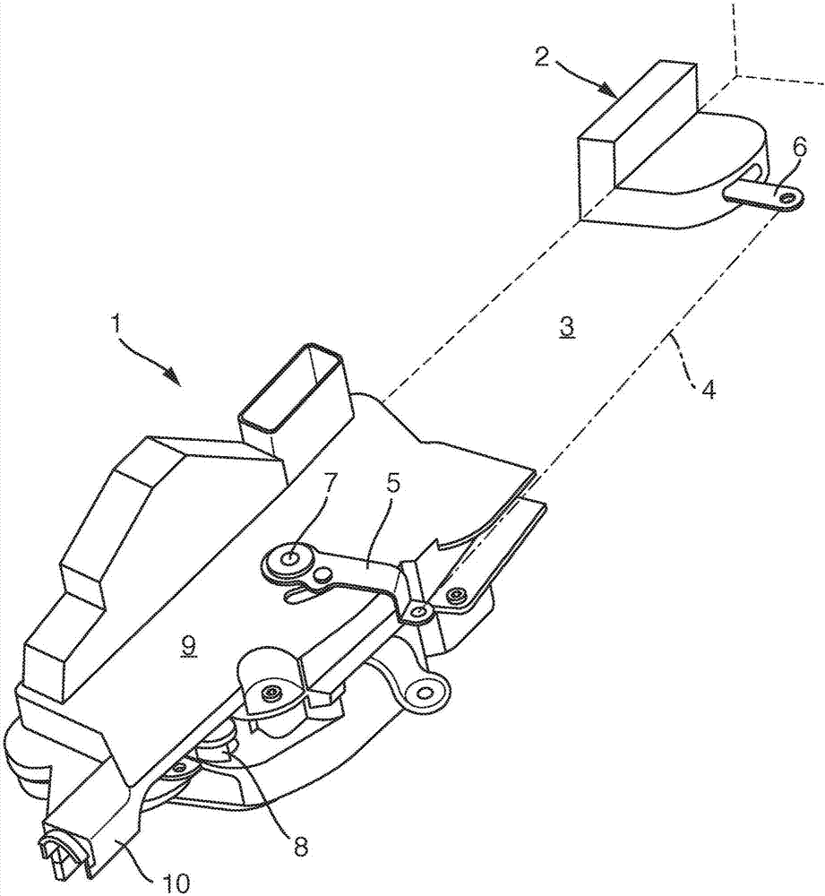
[0033] figure 1 A three-dimensional view of a motor vehicle door lock 1 is shown, wherein its basic position in a schematically shown sliding door 3 relative to another motor vehicle door lock 2 is shown. In this arrangement, the motor vehicle door lock 1 forms the main lock and the further motor vehicle door lock 2 forms the secondary lock 2 . Secondary lock 2 may also be referred to as additional lock 2 . A mechanical connection, which can be, for example, a Bowden cable 4 , is shown schematically between the main lock 1 and the auxiliary lock 2 . The Bowden cable 4 connects the second actuating lever 5 to the trigger lever and / or the actuating lever 6 on the additional lock 2 . The second actuating lever 5 is pivotably supported in the main lock 1 via a shaft 7 . The first actuating lever 8 is only partially visible here because it is covered by the housing cover 9 . The first actuating lever 8 can likewise be actuated, for example, via a Bowden cable, which is not show...


PUM


Abstract

The invention relates to a motor vehicle door lock (1) which comprises a locking mechanism having: a rotary latch and at least one pawl; a release lever (12); a locking device (21), the release lever (12) cooperating with the locking device (21) via a coupling lever (13); and an actuating lever (8), the locking mechanism being at least indirectly unlockable by means of the actuating lever (8). An additional motor vehicle door lock (2) is provided, and said vehicle door lock (2) can be actuated via a second coupling lever (14) and by means of the actuating lever (8), the first and the second coupling lever (13, 14) having a common pivot axis (15).

Description

technical field [0001] The invention relates to a motor vehicle door lock, the motor vehicle door lock has a locking mechanism, a trigger lever, a locking device, an operating lever, the locking mechanism has a rotary lock fork and at least one locking pawl, wherein the trigger lever is connected to the locking device through a coupling rod Together, wherein the locking mechanism can be unlocked at least indirectly by means of the actuating lever. Background technique [0002] Motor vehicle door locks are used to lock doors, hatches or hatches in motor vehicles. If it is common to use a door lock, for example for passenger cars, this is not the case, for example, when the dimensions of the door exceed certain dimensions. In order to ensure that larger doors are properly locked in any area of ​​the door opening, it may be necessary to use two or more door locks to properly lock the door. This is the case, for example, when the vehicle is not equipped with B-pillars, but the...

Claims


Application Information

Patent Timeline
Patent Type & Authority Applications(China)
IPC IPC(8): E05B79/20E05B81/06E05B81/16E05B81/36E05B83/40E05B77/32E05B85/20E05B63/14
CPCE05B63/143E05B77/32E05B79/20E05B81/06E05B81/16E05B81/36E05B83/40E05B85/20E05B15/1635E05B79/10
Inventor 于莫·因南
Owner KIEKERT AG
Why Eureka
Try Eureka