Quick connection structure for widening bridge floor system of bridge through UHPC material

A technology of fast connection and bridge deck system, which is applied in the direction of bridges, bridge parts, bridge materials, etc., can solve problems such as cracking in the rigid connection area of ​​the bridge deck, uneven settlement, and affecting the durability of the joint structure, so as to reduce on-site work quantity, avoidance of welding work, effect of quick connection

Pending Publication Date: 2017-10-20
SHANGHAI URBAN CONSTR DESIGN RES INST GRP CO LTD
View PDF12 Cites 4 Cited by
  • Summary
  • Abstract
  • Description
  • Claims
  • Application Information

AI Technical Summary

Problems solved by technology

However, since the new and old bridge structures usually set up independent piers and pile foundations, due to the uneven settlement of the new and old bridge foundations, cracks are prone to occur in the rigid connection area of ​​the bridge deck, which in turn affects the durability of the structure at the joints

Method used


Image

  • Quick connection structure for widening bridge floor system of bridge through UHPC material
  • Quick connection structure for widening bridge floor system of bridge through UHPC material
  • Quick connection structure for widening bridge floor system of bridge through UHPC material

Examples


Embodiment 1

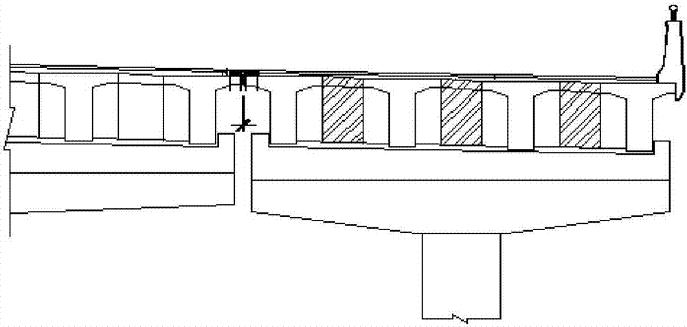
[0020] refer to Figure 4 As shown in the figure, a quick-connection structure of a widened bridge deck system using UHPC materials, including the existing bridge 1 and the newly built bridge 5, the upper end surface on the right side of the existing bridge 1 and the upper end surface on the left side of the newly built bridge 5 The L place is evenly inserted with a shearing steel bar 2, and a layer of UHPC concrete layer 4 is laid across the gap above the shearing steel bar 2, and a layer of asphalt concrete pavement layer 3 is laid on the upper end of the UHPC concrete layer 4, wherein, the length of L is 4000mm. A layer of conventional reinforced concrete pavement 6 is laid on the left upper end surface of the existing bridge 1 and the right upper end surface of the newly-built bridge 5, and a layer of asphalt concrete pavement 3 is laid on the upper end surface of the reinforced concrete pavement 6. .

[0021] In this embodiment, the side surface of the existing bridge s...

Embodiment 2

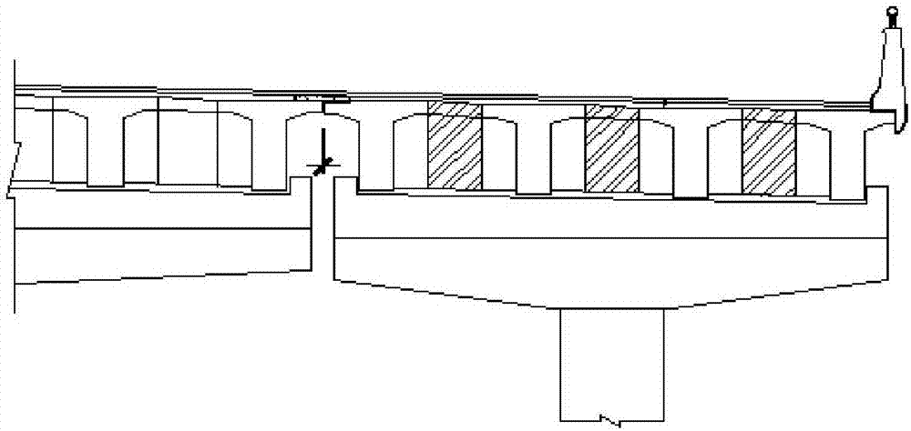
[0023] refer to Figure 5 As shown, the difference from Example 1 is that there is a wet joint section A between the existing bridge 1 and the newly built bridge 5 in the present situation, and the wet joint section A of the rigid connection between the old and new bridge decks adopts UHPC concrete 8 pouring. The distance between the new and old bridge deck rigidly connecting the wet joint section A is 200-300mm.

[0024] In this embodiment, the side girders of the existing bridge superstructure are drilled to expose the horizontal steel bars in the bridge deck, and vertical shear steel bars 2 are planted within a certain range on the top of the widened side beams. The superstructure of the newly built bridge 5 connects with the existing bridge 1 and the lateral bridge deck is reserved to reserve horizontally protruding steel bars to ensure that the staggered length of the horizontal steel bars excavated from the existing existing bridge 1 in the cross bridge direction after ...


PUM


Abstract

The invention discloses a quick connection structure for widening a bridge floor system of a bridge through a UHPC material. The structure comprises the current bridge and a newly-built bridge; bridge floors between the current bridge and the newly-built bridge are in rigid connection through wet connection sections made of the UHPC material or not connected; anti-shear reinforcing steel bars are evenly inserted in the L portion between the upper end face of the right side of the current bridge and the upper end face of the left side of the newly-built bridge; a UHPC concrete layer is laid over the anti-shear reinforcing steel bars in a joint-crossing mode, and an asphalt concrete pavement layer is laid at the upper end of the UHPC concrete layer, wherein the length of the L portion is 4000 mm. The structure has the advantages of being easy and convenient to construct, convenient to maintain and repair and better in durability.

Description

technical field [0001] This patent relates to a quick connection structure of bridge deck systems with widened bridges using UHPC materials. Background technique [0002] With the continuous development of traffic demand, there are more and more reconstruction projects for urban existing bridges. At present, the connection between new and old bridge structures mainly adopts ① as shown in the attached picture figure 1 As shown, the superstructures of the new and old bridges are not connected, and steel expansion joints are set at the longitudinal joints; ② See attached figure 2 As shown, the superstructures of the new and old bridges are not connected, and elastic-plastic expansion joints are set at the longitudinal joints; ③ See attached image 3 As shown, there are several splicing forms such as rigid connection and other superstructure decks of the new and old bridges. [0003] For the case of setting steel expansion joints, because the structure is not connected, ther...

Claims


Application Information

Patent Timeline
Patent Type & Authority Applications(China)
IPC IPC(8): E01D19/12E01D19/06E01D101/26
CPCE01D19/067E01D19/125E01D2101/26
Inventor 陆元春沙丽新郭卓明何晓光黄自杰俞露梁曾奇
Owner SHANGHAI URBAN CONSTR DESIGN RES INST GRP CO LTD
Why Eureka
Try Eureka