Ball-upper plate-anchor rod foundation and construction method thereof

An anchor rod foundation and anchor rod technology, which is applied in basic structure engineering, soil protection, construction and other directions, can solve the problems of unsatisfactory reinforcement effect, large amount of engineering, limited resistance, etc., to improve physical and mechanical properties, save investment, Effects of changing construction and foundation form

CN107268582AInactive Publication Date: 2017-10-20HENAN UNIV OF URBAN CONSTR
0 Cites 0 Cited by

Patent Information

Authority / Receiving Office
CN · China
Patent Type
Applications(China)
Current Assignee / Owner
Publication Date
2017-10-20
Estimated Expiration
Not applicable · inactive patent

Smart Images

  • Figure 1
    Figure 1
  • Figure 2
    Figure 2
  • Figure 3
    Figure 3
Patent Text Reader

Abstract

The invention relates to a ball-upper plate-anchor rod foundation. The ball-upper plate-anchor rod foundation comprises an upper plate embedded in a soil foundation, one or more anchor rods, cushion plates matched with the anchor rods, and anchor plates matched with the anchor rods, wherein the upper surface of the upper plate is flush with the ground. The upper plate is in a polygon shape, and first anchor rod holes are formed in the center of the upper plate. A third anchor rod hole is formed in the center of each cushion plate. Each anchor rod comprises a rod body, a base plate located at the lowest end of the rod body and a plurality of support rods hinged to the lower portion of the rod body, wherein waterproof explosive with a detonator is arranged below the base plate, and the multiple support rods are bundled to the periphery of the waterproof explosive. The bottom ends of the anchor rods, the base plates and the multiple support rods are anchored, the top ends of the anchor rods penetrate the first anchor rod holes in the corresponding positions of the upper plate and penetrate the third anchor rod holes of the cushion plates to be connected with the anchor plates together. The invention further discloses a construction method of the foundation. According to the ball-upper plate-anchor rod foundation and the construction method of the foundation, the structure is simple, the construction and foundation form is basically changed, the investment is obviously saved, and abandoned soil is reduced.
Need to check novelty before this filing date? Find Prior Art

Description

technical field

[0001] The invention relates to soil foundation reinforcement and foundation forms, in particular to a ball-upper plate-bolt foundation and a construction method thereof. Background technique

[0002] At present, most of the foundations are compression foundations, that is, the foundation mainly bears the vertical load imposed by the superstructure and meets the deformation and stability requirements, typically including independent foundations, strip foundations, raft foundations, etc. The uplift-resistant foundation mainly includes large excavation foundation, excavation and bottom expansion foundation, explosive expansion pile foundation, etc. difficulty, and there are problems such as large amount of engineering, long time-consuming, high cost, great damage to the environment, but limited resistance and unsatisfactory reinforcement effect. The large deformation and the stability of the foundation become the key issues that must be solved. Contents of t...

Examples

Embodiment Construction

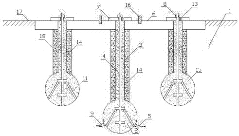
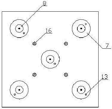
[0041] Such as Figure 1~4 Shown, a kind of ball-upper plate-bolt foundation, it comprises an upper plate 6 embedded in the foundation 1 and the upper surface is flush with the ground 17, one or more anchor rods 4 and matching with the anchor rods 4 Backing plate 7 and anchor plate 8.

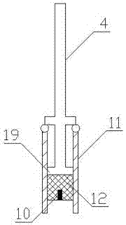
[0042] The upper plate 6 is polygonal (polygons include triangles, quadrilaterals, ...), with an anchor hole I in the center; an anchor hole III in the center of the backing plate 7; the anchor 4 includes a rod body and a chassis at the bottom of the rod body 19 and several support rods 11 hinged with the lower part of the rod body; the water-resistant explosive 12 with detonator 10 is installed under the chassis 19, and several support rods 11 are bound around the water-resistant explosive 12; the bottom of the anchor rod 4 and The chassis 19 and several support rods 11 are all anchored, and their top ends pass through the anchor hole I corresponding to the upper plate 6 respectively, and pas...