Soil foundation center and slab angle multi-cable anti-uplift foundation and construction method thereof

A soil foundation and slab angle technology, which is applied in basic structure engineering, sheet pile walls, blasting, etc., can solve the problems of unsatisfactory reinforcement effect, limited resistance, and large amount of engineering, so as to improve physical and mechanical properties, safety, and saving. effect of investment

Pending Publication Date: 2017-10-20
HENAN UNIV OF URBAN CONSTR
View PDF7 Cites 0 Cited by
  • Summary
  • Abstract
  • Description
  • Claims
  • Application Information

AI Technical Summary

Problems solved by technology

The uplift-resistant foundations mainly include large excavation foundations, excavation and bottom expansion foundations, and explosive expansion pile foundations, etc. It is difficult, and there are problems such as large amount of engineering, long time consumption, high cost, great damage to the environment, limited resistance, and unsatisfactory reinforcement effect. The above problems are more prominent under the condition of the soil foundation, and the soil The large deformation and the stability of the foundation become the key issues that must be solved

Method used


Image

  • Soil foundation center and slab angle multi-cable anti-uplift foundation and construction method thereof
  • Soil foundation center and slab angle multi-cable anti-uplift foundation and construction method thereof
  • Soil foundation center and slab angle multi-cable anti-uplift foundation and construction method thereof

Examples


Embodiment Construction

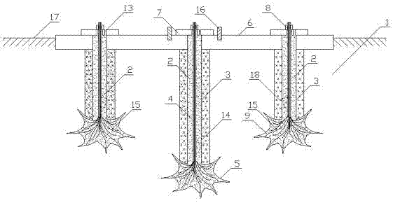
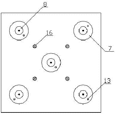
[0034] Such as Figure 1~3 As shown, the center of the foundation and the multi-cable pullout foundation at the corner of the board include an upper plate 6 embedded in the foundation 1 and the upper surface of which is higher than the ground 17, a plurality of hair bolts 4 and supporting bolts 4 Backing plate 7 and anchor plate 8.

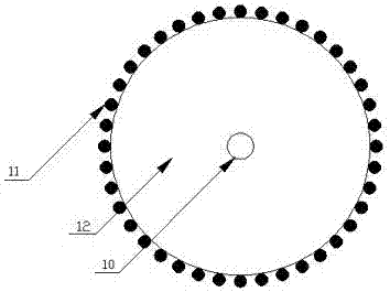
[0035] The upper plate 6 is polygonal, and its center and each corner are arranged with an anchor hole I; the center of the backing plate 7 is provided with an anchor hole II; the bottom ends of several hair anchors 4 are anchored, and the top ends pass through The anchor hole I of the upper plate 6 is connected to the anchor plate 8 through the anchor hole II of the backing plate 7; Deformed steel wire or (and) other wires. The lower part of the tensile filament 11 is bundled with the water-resistant explosive 12 equipped with the detonator 10 , and the tensile filament 11 is evenly distributed around the water-resistant explosive 12 equipped w...


PUM


Abstract

The invention relates to a soil foundation center and slab angle multi-cable anti-uplift foundation. The soil foundation center and slab angle multi-cable anti-uplift foundation comprises an upper plate, a plurality of beard and hair anchor rods, base plates and anchor plates, wherein the upper plate is embedded into a soil foundation and the upper surface of the upper plate is higher than the ground; and the base plates and the anchor plates are matched with the beard and hair anchor rods. The upper plate is a polygon, and the center and each angle of the polygon are each provided with an anchor rod hole I. The center of each base plate is provided with an anchor rod hole II. The bottom ends of the multiple beard and hair anchor rods are all anchored, and the top ends of the beard and hair anchor rods penetrate through the anchor rod holes I of the upper plate and the anchor rod holes II of the base plates to be connected together with the corresponding anchor plates. The beard and hair anchor rods are composed of tension thin wires. Water-resistant explosives filled with detonators are bundled on the lower portions of the corresponding tension thin wires, and the tension thin wires are evenly distributed on the peripheries of the water-resistant explosives filled with the detonators in the perimeter direction. The invention further discloses a construction method of the soil foundation center and slab angle multi-cable anti-uplift foundation. According to the soil foundation center and slab angle multi-cable anti-uplift foundation and the construction method thereof, the structure is simple, the construction and foundation modes are changed fundamentally, investment is reduced and waste soil is also reduced.

Description

technical field [0001] The invention relates to soil foundation reinforcement and foundation forms, in particular to multi-cable uplift foundations at the center of the foundation and board corners and a construction method thereof. Background technique [0002] At present, most of the foundations are compression foundations, that is, the foundation mainly bears the vertical load imposed by the superstructure and meets the deformation and stability requirements, typically including independent foundations, strip foundations, raft foundations, etc. The uplift-resistant foundation mainly includes large excavation foundation, excavation and bottom expansion foundation, explosive expansion pile foundation, etc. It is difficult, and there are problems such as large amount of engineering, long time consumption, high cost, great damage to the environment, limited resistance, and unsatisfactory reinforcement effect. The above problems are more prominent under the condition of the so...

Claims


Application Information

Patent Timeline
IPC IPC(8): E02D27/14E02D27/50E02D5/54F42D3/00
CPCF42D3/00E02D5/54E02D27/14E02D27/50E02D2250/00E02D2300/0073
Inventor 言志信
Owner HENAN UNIV OF URBAN CONSTR
Why Eureka
Try Eureka