
Sprue cap

A nozzle and liquid injection technology, applied in the field of filler caps, can solve the problems of fuel leaking out of the vehicle and foreign matter mixed into the tank, etc.

Active Publication Date: 2020-09-25
U SHIN LTD
View PDF4 Cites 0 Cited by
  • Summary
  • Abstract
  • Description
  • Claims
  • Application Information

AI Technical Summary

Problems solved by technology

If such a situation of forgetting to install the filler cap occurs, fuel may leak out of the vehicle or foreign matter may enter the tank

Method used


Image

  • Sprue cap
  • Sprue cap
  • Sprue cap

Examples


no. 1 approach

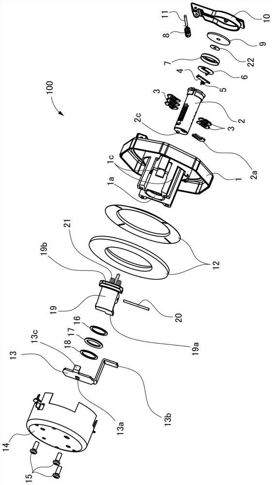
[0071] figure 1 It is an exploded perspective view of the sprue cap according to this embodiment.

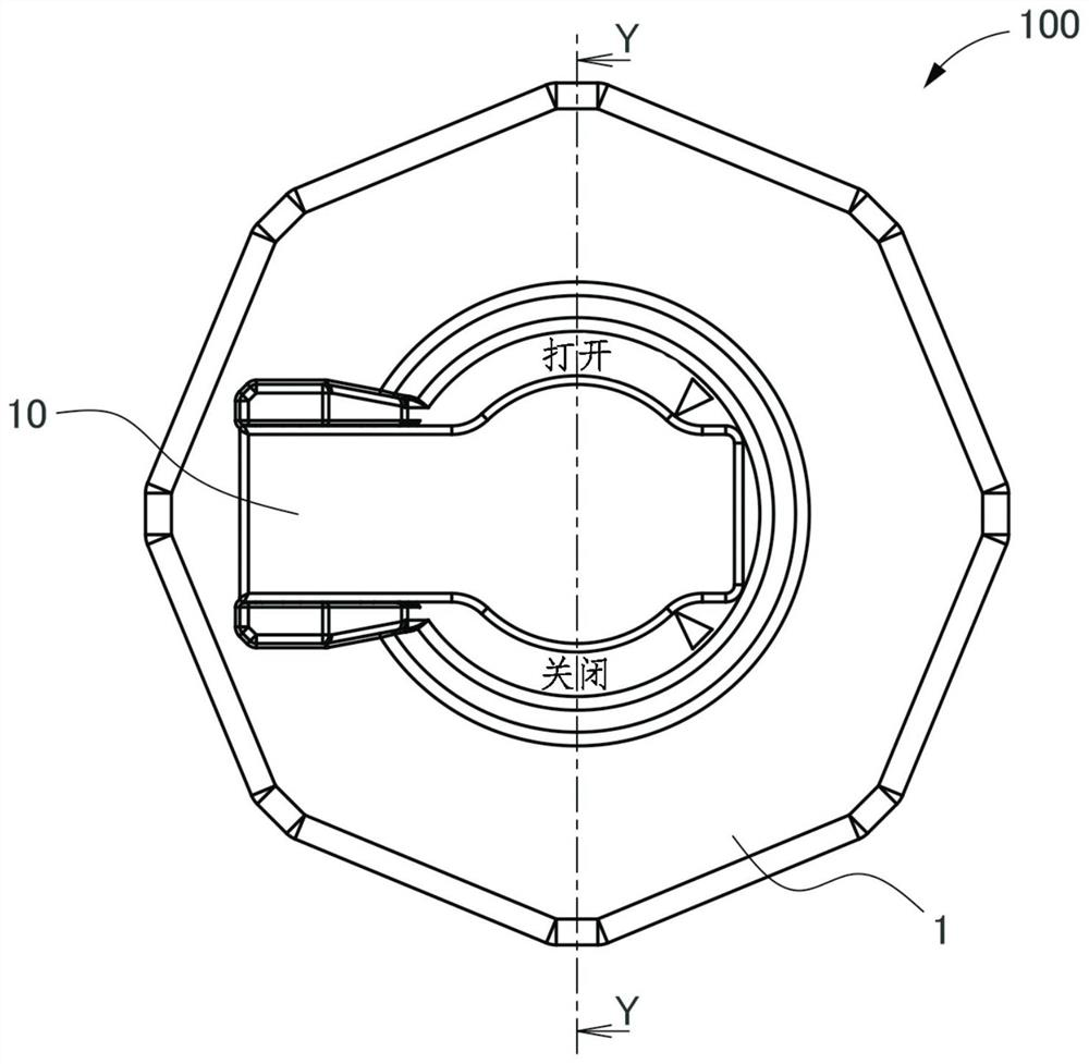
[0072] figure 2 is a front view of the sprue cap 100 .

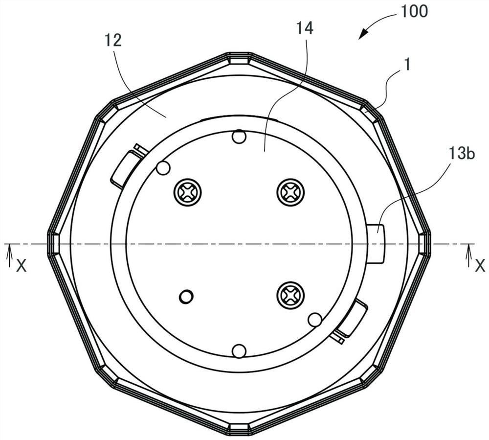
[0073] image 3 is a rear view of the sprue cap 100 .

[0074] Figure 4 is in figure 2 The cross-sectional view after cutting the sprue cover 100 at the position of the arrow YY in .

[0075] Figure 5 is in image 3 The cross-sectional view of the sprue cover 100 is cut at the position of the arrow XX in the figure.

[0076] In addition, in the following description, although specific numerical values, shapes, materials, etc. are shown and demonstrated, these can be changed suitably.

[0077] Also, in the description below, figure 1 middle right, Figure 4 middle left, figure 2 in front of the eyes, image 3 The depth side in is set to "Front", figure 1 middle left, Figure 4 middle right, figure 2 in the depth side, image 3 In the description, the front side in front of the eye is referred to as "r...

no. 2 approach

[0128] Figure 14 It is a perspective view showing the sprue cap 200 of the second embodiment in a state attached to the injection pipe P and in which the core body 2 is located at the locked position.

[0129] In the second embodiment, the restricting member 219 is used as a member that moves linearly, and the locking portion 213c of the locking member 213 is provided further forward than the first embodiment, which is the main difference from the first embodiment. change. In addition, the sprue cap 200 of the second embodiment is the same as that of the first embodiment except that the forms of the locking member 213, the restricting member 219, and the return spring 221 are different from those of the first embodiment. Therefore, parts that realize the same functions as those in the first embodiment described above are assigned the same symbols, and redundant descriptions are appropriately omitted.

[0130] The locking member 213 is formed by pressing a sheet metal materi...


PUM


Abstract

The invention provides a filler cap which can prevent the phenomenon that a vehicle is started without installation of a filler cap. The filler cap (100) is provided with a limiting component (19) which restrains the movement of a locking part to a locking position under the condition that the filler cap is not installed on a filler pipe (P). The limiting component (19) can prevent a core body (2) from rotating to the locking position allowing a key (K) to be pulled out. Thus, only when the filler cap (100) is installed on the filler pipe (P) and the core body (2) is rotated to the locking position can the key (K) be pulled out.

Description

technical field [0001] The invention relates to a sprue cap. Background technique [0002] The cap of the liquid injection port (fuel injection port, etc., hereinafter referred to as the injection pipe) formed on the tank of a vehicle such as a tractor, that is, the sprue cap is used in the following manner: it is removed when fuel is injected, and it is attached to the injection pipe at other times. . In order to prevent the filler cap from falling off or fuel from being stolen, there is known a technique in which a locking mechanism is provided on the filler cap, and a core body serving as the locking mechanism is rotated by an engine start key to be detachable (see Patent Document 1). . [0003] With this type of filler cap, if the key can be pulled out from the filler cap removed during fuel injection, even if you forget to attach the filler cap to the injection pipe after fuel injection, you can start the engine with the key and start the car. If such a situation of ...

Claims


Application Information

Patent Timeline
Patent Type & Authority Patents(China)
IPC IPC(8): E05B83/34B60K15/05
CPCB60K15/05B60K2015/0561E05B83/34B60K15/0409B60K2015/0412
Inventor 中岛正彦
Owner U SHIN LTD
Learn More