pump device

A pump device and technology for generating devices, which are applied in the directions of pumps, components of pumping devices for elastic fluids, pump elements, etc., can solve problems such as expensive devices and the like

Active Publication Date: 2019-07-12
DANFOSS AS
View PDF8 Cites 0 Cited by
  • Summary
  • Abstract
  • Description
  • Claims
  • Application Information

AI Technical Summary

Problems solved by technology

For this, a large number of pump units are required, which makes the whole unit expensive
In addition, each pump unit used with a corresponding drive motor requires a certain amount of space
Therefore, in order to pursue a large fluid volume to be pressurized, considerable space is required

Method used


Image

  • pump device
  • pump device
  • pump device

Examples


Embodiment Construction

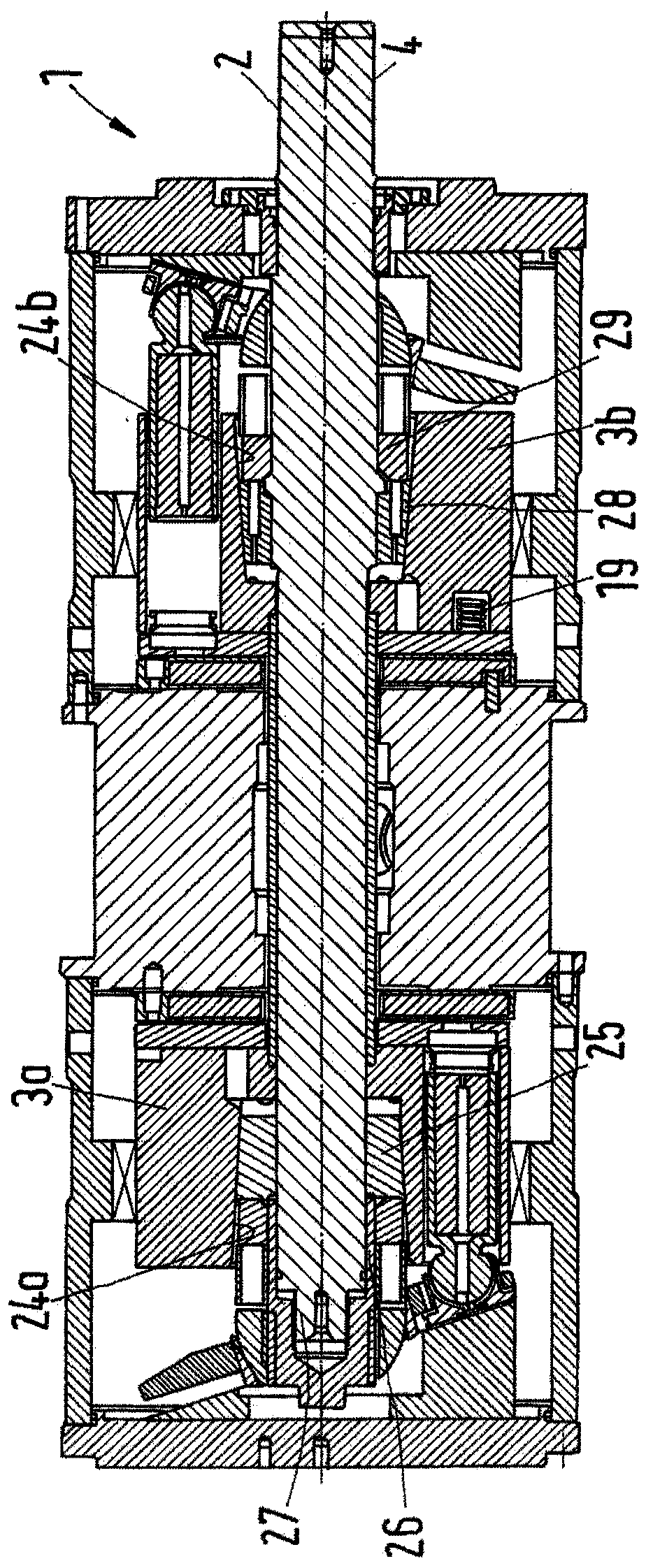
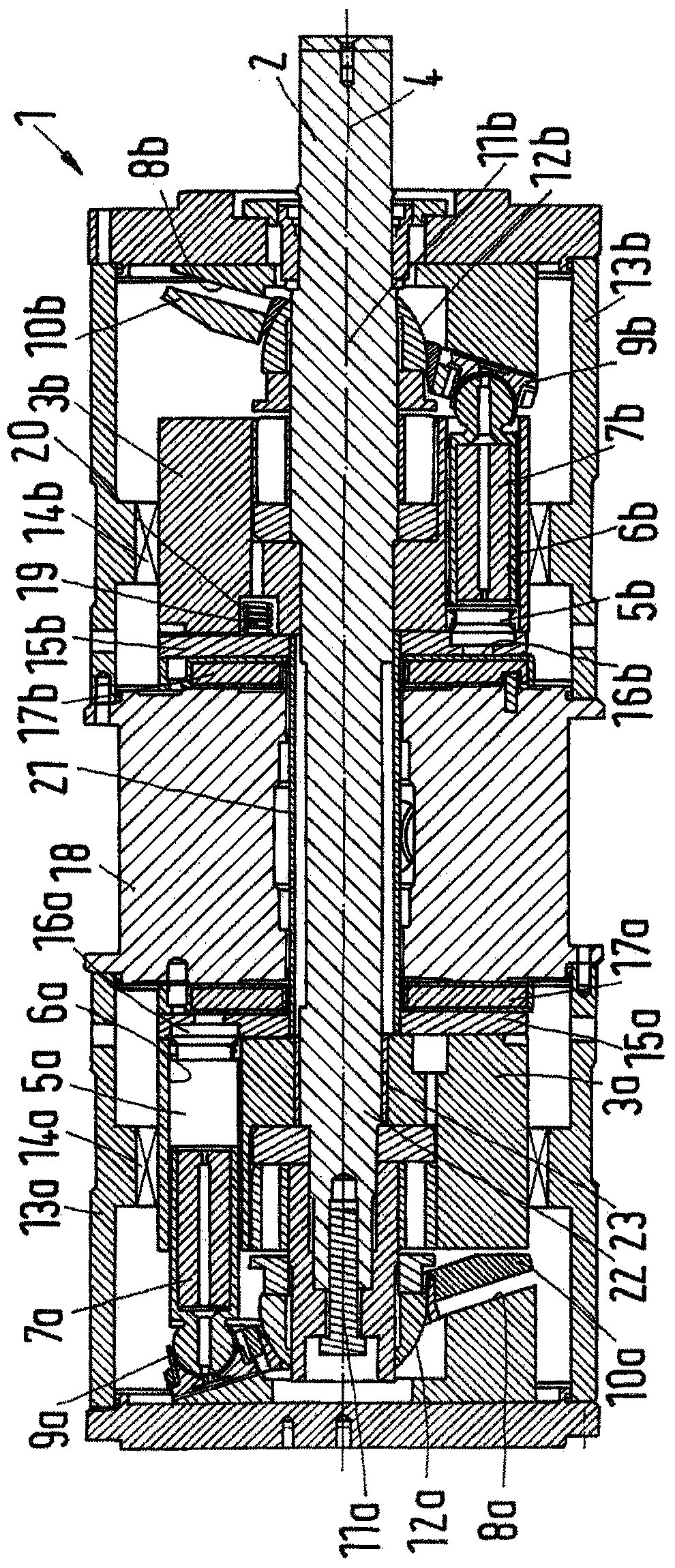
[0025] The pump device 1 is used to pump water. It is a water hydraulic machine and comprises a shaft 2 which is rotatable by a motor not shown. The shaft 2 is a through-shaft extending almost the entire length of the pump device 1 . The first rotor 3 a and the second rotor 3 b are fixed to the shaft 2 in the direction of rotation and in the axial direction of the shaft 2 , which refers to the axis of rotation 4 of the shaft 2 .

[0026] The first rotor 3a has a plurality of first pressure chambers 5a. Each pressure chamber 5a is formed by a first cylinder 6a and a first piston 7a which is movable parallel to the axis 4 of the shaft 2 during operation. Thus, the volume of the first pressure chamber 5 a changes between a maximum size and a minimum size during the rotation of the shaft 2 .

[0027] The first swash plate 8a is positioned facing the front of the first rotor 3a. Each first piston 7a is provided with a first slide 9a. The slider 9a is held in contact with the s...


PUM


Abstract

A pump device (1) comprising: a shaft (2), rotor means (3a, 3b), port plate means (15a, 15b) and valve plate means (17a, 17b). The rotor device (3a, 3b) comprises a first rotor (3a) and a second rotor (3b), the first rotor (3a) has a first pressure chamber (5a), the second rotor (3b) There is a second pressure chamber (5b), the port plate arrangement (15a, 15b) has a first port plate (15a) and a second port plate (15b), and the valve plate arrangement (17a, 17b) has a first valve plate (17a) and a second valve plate (17b), wherein at least one rotor comprises force generating means (19), said force generating means ( 19) Press the second port plate (15b) against the second valve plate (17b). The pump device of the present invention pressurizes large volumes of fluid, especially water, in a confined space.

Description

technical field [0001] The invention relates to a pump device. In particular, the present invention relates to a water hydraulic pumping device, ie a pumping device with which water can be pumped and with which the water pressure can be increased significantly so that water can be supplied to a reverse osmosis device. Background technique [0002] The pump arrangement comprises a shaft, a rotor arrangement fixed to said shaft in the direction of rotation, said rotor arrangement having a pressure chamber whose volume changes during rotation of said rotor arrangement, port plate arrangement, Said port plate means has a through opening for each of said pressure chambers and is connected in rotational direction to said rotor means, and to a valve plate means cooperating with said port plate means. [0003] In such a pump arrangement, when the shaft is driven in the direction of rotation, the rotor arrangement rotates, thereby increasing and decreasing the volume of the pressure...

Claims


Application Information

Patent Timeline
Patent Type & Authority Patents(China)
IPC IPC(8): F04B1/12F04B53/10
CPCF04B1/2021F04B1/22F04B53/10
Inventor 威尔曼·弗里德里克森弗兰克·霍尔姆·伊韦尔森拉尔斯·马腾森帕列·奥尔森斯蒂格·凯尔德加德·安德森
Owner DANFOSS AS
Why Eureka
Try Eureka