
A standard sample for calibration measurement of fluorescence instruments and preparation method thereof

A technology for calibration measurement and standard sample, applied in the field of fluorescence instrument calibration measurement, can solve the problems of inability to precisely control the consistency of the thickness of the fluorescent material film, inability to produce small-scale graphics with complex patterns, and inability to accurately control the fluorescence intensity, etc. The effect of optimizing the calibration measurement process, improving usability, increasing complexity and sophistication

Active Publication Date: 2019-11-29
NAT INST OF METROLOGY CHINA
View PDF4 Cites 0 Cited by
  • Summary
  • Abstract
  • Description
  • Claims
  • Application Information

AI Technical Summary

Problems solved by technology

However, it cannot accurately control the thickness consistency of the fluorescent material film with different concentrations of the standard sample, resulting in the inability to accurately control the actual fluorescence intensity and affect the calibration measurement results
In addition, the standard samples obtained in this way can only produce large-scale circular graphics, and cannot produce small-scale graphics with complex patterns

Method used


Image

  • A standard sample for calibration measurement of fluorescence instruments and preparation method thereof
  • A standard sample for calibration measurement of fluorescence instruments and preparation method thereof
  • A standard sample for calibration measurement of fluorescence instruments and preparation method thereof

Examples


Embodiment 1

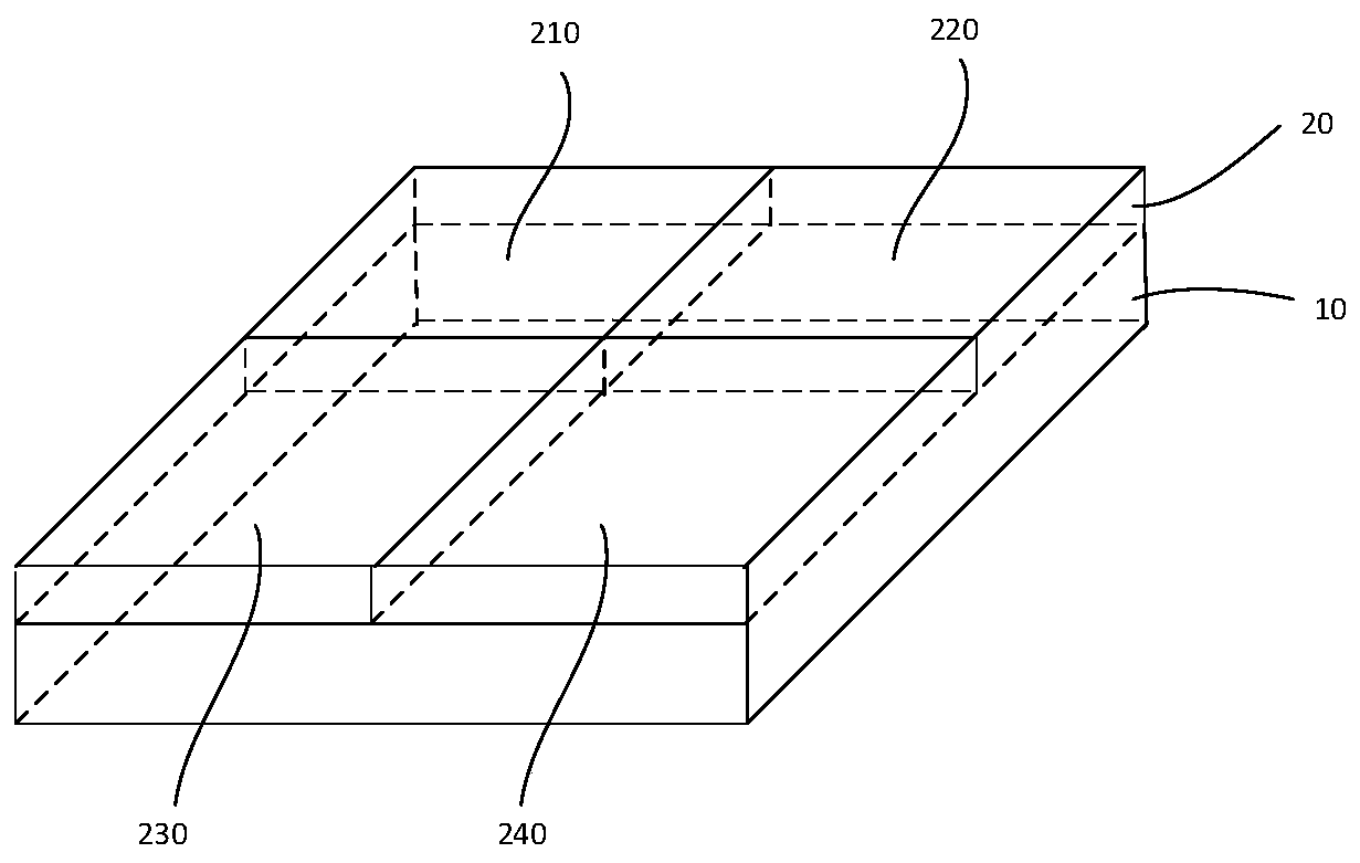
[0040] Such as figure 1 As shown, a standard sample used for calibration and measurement of a fluorescent instrument includes a substrate 10 and a fluorescent film 20. The fluorescent film 20 is disposed on the substrate 10 and includes a plurality of fluorescent intensity regions with different fluorescent intensities, and each of the plurality of fluorescent intensity regions has a specific fluorescent dye filling duty ratio.

[0041] It should be noted that, in the present invention, that each of the plurality of fluorescence intensity regions has a specific fluorescent dye filling duty ratio means that different fluorescent intensity regions have different fluorescent dye filling duty ratios.

[0042] In this embodiment, the substrate 10 is a glass substrate, and the fluorescent film 20 includes, for example, four fluorescence intensity regions, which are a first fluorescence intensity region 210, a second fluorescence intensity region 220, a third fluorescence intensity region ...

Embodiment 2

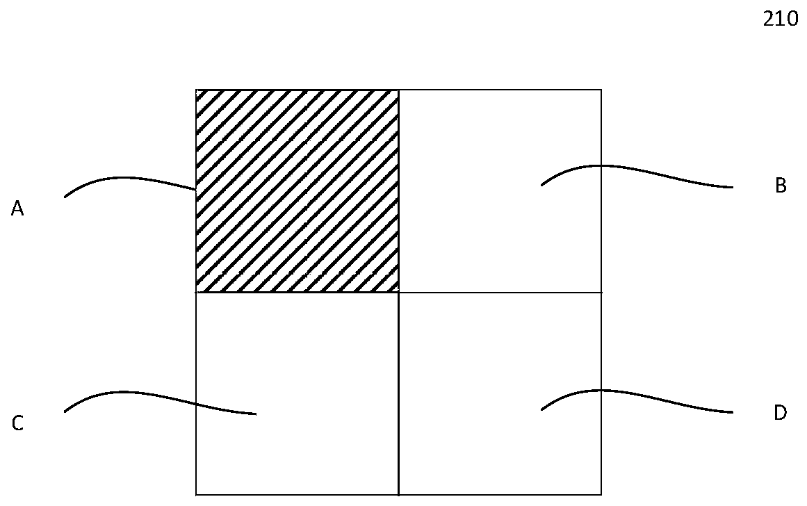
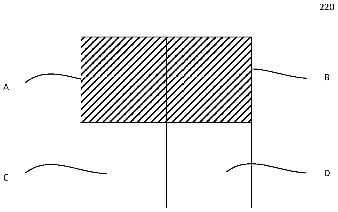
[0045] A standard sample used for calibration and measurement of a fluorescent instrument includes a substrate 10 and a fluorescent film 20. The fluorescent film 20 is disposed on the substrate 10 and includes a plurality of fluorescent intensity regions with different fluorescent intensities, the fluorescent intensity region includes a plurality of repeating units corresponding to pixels, and the repeating units in the same fluorescent intensity region have the same fluorescent dye filling Duty cycle.

[0046] Such as Figure 2-Figure 5 As shown, in this embodiment, for example, the fluorescent film 20 includes four fluorescent intensity regions, namely a first fluorescent intensity region 210, a second fluorescent intensity region 220, a third fluorescent intensity region 230, and a fourth fluorescent intensity region 240. For example, the first fluorescence intensity region 210 includes m first repeating units, the second fluorescence intensity region 220 includes n second re...

Embodiment 3

[0051] On the basis of the above-mentioned embodiment 1 and embodiment 2, in order to improve the firmness of the inorganic fluorescent material on the substrate, a protective layer can be coated on the surface of the substrate on which the fluorescent film is formed. The commonly used protective layer is polymethylsiloxane (PDMS ) Film or polyvinyl alcohol (PVA) film and other transparent low-fluorescence background film, the thickness of the film should be less than 50 microns.


PUM


Abstract

The invention discloses a standard sample wafer for calibration measurement of fluorescent instruments. The standard sample wafer comprises a substrate and a fluorescent film, wherein the fluorescent film is arranged on the substrate and comprises a plurality of fluorescent intensity regions having different fluorescent intensities; and each fluorescent intensity region has a specific fluorescent dye filling duty cycle. The invention also discloses a preparation method of the standard sample wafer for the calibration measurement of the fluorescent instruments. The standard sample wafer for the calibration measurement of the fluorescent instruments and the preparation method of the standard sample wafer provided by the invention accurately control and adjust the fluorescent dye filling duty cycle in a region corresponding to each pixel on the surface of the fluorescent film by using a micro-nano machining technology, and acquire a plurality of fluorescent intensity regions having the same thickness; and each fluorescent intensity region has accurately specific fluorescent dye filling duty cycle, so that small-sized graphs of a complicated pattern are possibly obtained.

Description

Technical field [0001] The invention relates to the calibration measurement of a fluorescent instrument. More specifically, it relates to a standard sample used for calibration measurement of a fluorescent instrument and a preparation method thereof. Background technique [0002] With the continuous development of biotechnology, fluorescent detection technology (Fluorescent Detection) has been widely used in life sciences, medicine and hygiene, food safety, pharmacology due to its characteristics of fluorescence quantification, stable results, high sensitivity, closed operation, safety and convenience. The fields of science and biochemical analysis. Fluorescence detection is a kind of natural luminescence reaction, through the reaction of luciferase and ATP, the light intensity is measured by special equipment and expressed in digital form, and the reaction result can be obtained quickly, which can be used to detect human cells, bacteria, molds, food residues, etc. . [0003] Tr...

Claims


Application Information

Patent Timeline
Patent Type & Authority Patents(China)
IPC IPC(8): G01N21/64
CPCG01N21/6428
Inventor 钟源李劲劲张玲王晶钟青王雪深傅博强王兰若
Owner NAT INST OF METROLOGY CHINA
Learn More