Motor and method of manufacturing the motor
A manufacturing method and motor technology, applied in the manufacture of motor generators, manufacture of stator/rotor body, magnetic circuit shape/style/structure, etc., can solve problems such as difficult rotor magnet fixation, support component deformation, rotor magnet deformation, etc. Improvement of productivity, suppression of deformation, and easy management of dimensional accuracy are achieved
- Summary
- Abstract
- Description
- Claims
- Application Information
AI Technical Summary
Problems solved by technology
Method used
Image
Examples
no. 1 Embodiment approach >
[0023]
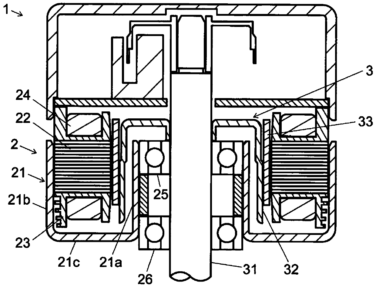
[0024] A schematic configuration of a motor according to an exemplary first embodiment of the present invention will be described. figure 1 It is a cutaway longitudinal end view of the motor according to the first embodiment of the present invention. figure 1 The motor 1 shown has a stator 2 and a rotor 3 .
[0025] The stator 2 is formed in an annular shape. The stator 2 has a stator housing 21 . The stator case 21 has an inner cylinder part 21a, an outer cylinder part 21b, and a connection part 21c. The inner cylinder part 21a is formed in the hollow cylindrical shape centering on a rotating shaft. The outer cylinder portion 21b is formed in a cylindrical shape centered on the rotation axis. The inner cylinder part 21a and the outer cylinder part 21b are formed coaxially. The outer cylinder portion 21b is disposed radially outward of the inner cylinder portion 21a. The connecting portion 21c is formed in a disk shape centered on the rotation axis, and connec...
no. 2 Embodiment approach >
[0077]
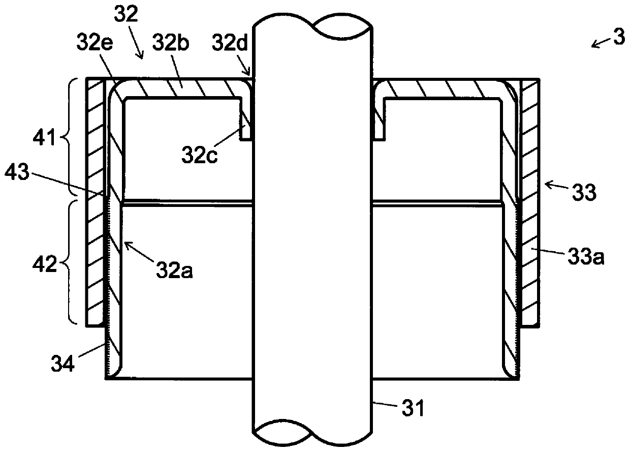
[0078] Next, a motor according to an exemplary second embodiment of the present invention will be described. Figure 6 It is a partially enlarged longitudinal sectional view of a rotor of a motor according to a second embodiment of the present invention. In addition, since the basic structure of this embodiment is the same as that of the first embodiment described above, the same reference numerals or the same names as those of the first embodiment may be assigned to the same constituent elements as before, and description thereof may be omitted.
[0079] The rotor 3 has a protruding portion 34 radially protruding from the holder cylindrical portion 32a. The protruding portion 34 is formed in a region adjacent to the flange portion 32b in the axial direction. The protruding portion 34 protrudes radially outward from the outer peripheral surface of the holder cylindrical portion 32a.
[0080] The cage 32 has a separation portion 41 and a fitting portion 42 that are...
no. 3 Embodiment approach >
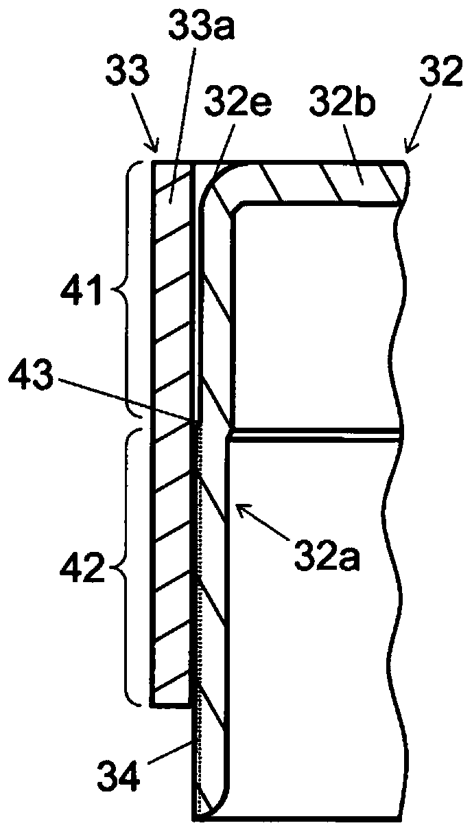
[0094] Next, a motor according to an exemplary third embodiment of the present invention will be described. Figure 8 It is a partially enlarged longitudinal sectional view of a rotor of a motor according to a third embodiment of the present invention. In addition, since the basic structure of this embodiment is the same as that of the first embodiment described above, the same reference numerals or the same names as those of the first embodiment may be assigned to the same constituent elements as before, and description thereof may be omitted.
[0095] The rotor 3 has a protruding portion 34 radially protruding from the holder cylindrical portion 32a. The protruding portion 34 is formed in a region away from the flange portion 32b in the axial direction. The protruding portion 34 protrudes radially outward from the outer peripheral surface of the holder cylindrical portion 32a.
[0096] The cage 32 has a separation portion 41 and a fitting portion 42 that are continuous in ...
PUM
 Abstract
Description
Claims
Application Information
 - R&D
- Intellectual Property
- Life Sciences
- Materials
- Tech Scout
- Unparalleled Data Quality
- Higher Quality Content
- 60% Fewer Hallucinations
Browse by: Latest US Patents, China's latest patents, Technical Efficacy Thesaurus, Application Domain, Technology Topic, Popular Technical Reports.
© 2025 PatSnap. All rights reserved.Legal|Privacy policy|Modern Slavery Act Transparency Statement|Sitemap|About US| Contact US: help@patsnap.com


