Punching scrap outputting device

A technology of exporting device and scrap, applied in the field of stamping equipment, can solve the problem that stamping scrap cannot be exported in time, and achieve the effect of shortening the sliding stroke

Active Publication Date: 2017-10-24
柳州市西菱机械有限公司
View PDF4 Cites 4 Cited by
  • Summary
  • Abstract
  • Description
  • Claims
  • Application Information

AI Technical Summary

Problems solved by technology

[0003] The purpose of the present invention is to provide a stamping waste exporting device, which can solve the problem that the existing stamping waste cannot be exported in time

Method used


Image

  • Punching scrap outputting device
  • Punching scrap outputting device

Examples


Embodiment Construction

[0014] The present invention will be described in further detail below in conjunction with accompanying drawing embodiment:

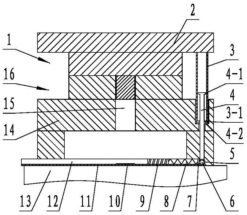
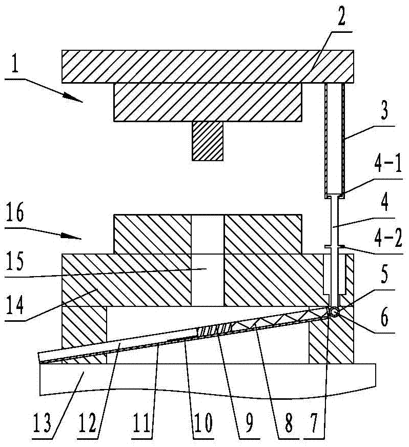
[0015] figure 1 and figure 2 The shown punching waste exporting device mainly includes a material receiving plate 11, a push block 9, a spring 8, a positioning pin sleeve 5, a pin shaft 6, a lifting rod 7 and a guide sleeve 3, and the material receiving plate 11 is arranged on the workbench 13 and Located below the lower die base 14, in order to facilitate the smooth export of punched waste 10, the length direction of the material receiving plate 11 is set along the width direction of the worktable 13, and one end of it stretches out from the edge of the workbench 13 as a discharge end, and the other end is provided with an end plate 7 , a positioning pin sleeve 5 is fixed on the outside of the end plate 7, and a pin shaft 6 is inserted in the positioning pin sleeve 5. The pin shaft 6 is hinged with a vertically arranged lifting rod 4, and the lifting...


PUM


Abstract

The invention discloses a punching scrap outputting device, and relates to the technical field of punching equipment. The device comprises a material holding plate which is arranged above a worktable and positioned under a lower die holder, wherein one end of the material holding plate extends out of the edge of the worktable and is used as a discharging end; the other end of the material holding plate is connected with a positioning pin sleeve; a pin shaft is mounted in the positioning pin sleeve in an inserting manner; the pin shaft is hinged to a vertically-arranged lifting rod; the lifting rod penetrates through a lower die and is connected with a guide sleeve fixed on an upper template; and limiting structures are respectively arranged on the lifting rod and the guide sleeve. According to the punching scrap outputting device disclosed by the invention, the problem that existing punching scraps cannot be output in time is solved.

Description

technical field [0001] The invention relates to the technical field of stamping equipment, in particular to a stamping waste exporting device. Background technique [0002] When performing stamping operations such as punching, blanking, trimming, and sectioning on the workpiece to achieve separation, a lot of waste will be generated. If it cannot be cleaned up in time, it will affect the normal stamping operation. Because, during the stamping production process, the generated waste slides through the blanking hole to between the lower die base and the punching machine table. In the space formed by the support pads, the height of the space is low. It may be stacked to block the waste hole, and the blanking will not be smooth if the production continues, causing the waste to bounce back, which is very likely to damage the surface quality of the stamping part, causing the punch and template to crack, or causing the laminated stamping to cause the knife edge to crack like a bloc...

Claims


Application Information

Patent Timeline
Patent Type & Authority Applications(China)
IPC IPC(8): B21D45/04
CPCB21D45/04
Inventor 梁宇松
Owner 柳州市西菱机械有限公司
Why Eureka
Try Eureka