

Combined type milling cutter
A combined milling cutter technology, which is applied in the direction of milling cutters, milling machine equipment, manufacturing tools, etc., can solve the problems of easy wear of drill bits, wear of milling cutter heads, and impact on tool life, so as to avoid direct wear and avoid excessive Abrasion and the effect of improving the service life
- Summary
- Abstract
- Description
- Claims
- Application Information
AI Technical Summary
Problems solved by technology
Method used
Image

Examples
Embodiment 1
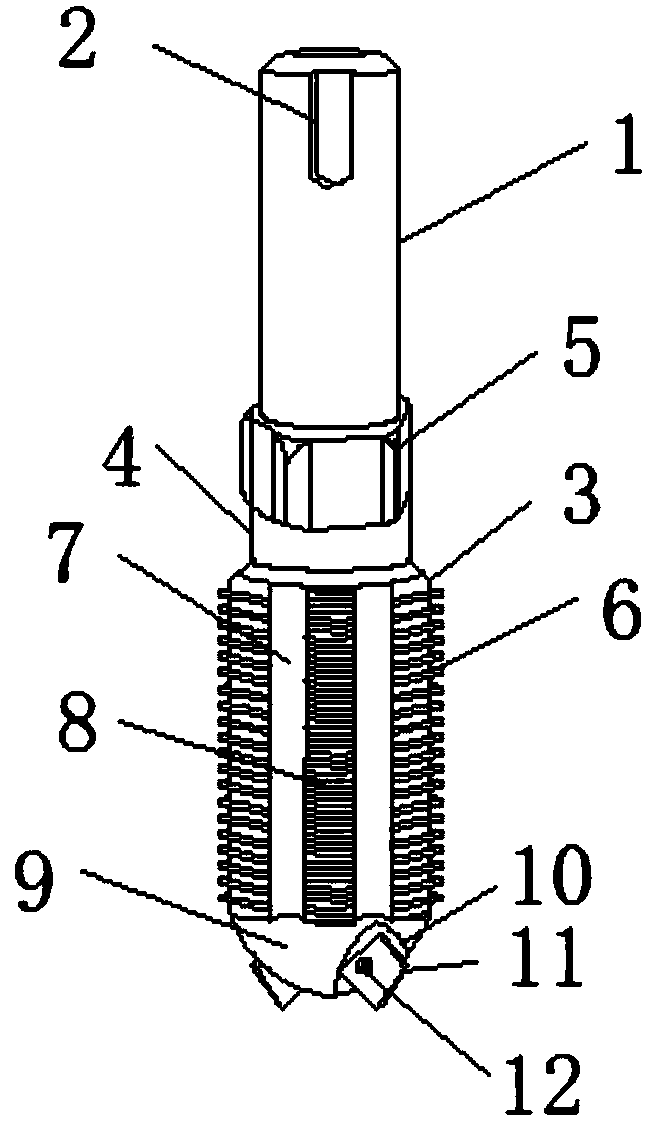
[0020] see figure 1 with figure 2 As shown, a combined pin milling cutter includes a main shaft 1, a rotating body 3, a cutting edge 6 and a drill bit 9. The main shaft 1 is provided with a card slot 2, and the card slot 2 is U-shaped, which is convenient for the card connection of the transmission device. , to avoid sliding during the rotation process, the upper end of the rotating body 3 is connected to the connecting cylinder 4, the upper end of the connecting cylinder 4 is connected to the connecting nut 5, and the connecting nut 5 is provided with a thread matching one end of the main shaft 1, which is used for the connecting nut 5 connection, the rotating body 3 is provided with a cutting edge 6, the cutting edge 6 is used for cutting and milling of the material, the rotating body 3 is provided with a chip guide groove 7, and a plurality of chip guide grooves 7 are evenly arranged to export the debris of the material , the rotating body 3 is connected with a brush 8, t...
Embodiment 2
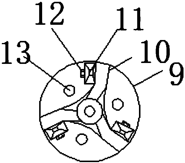
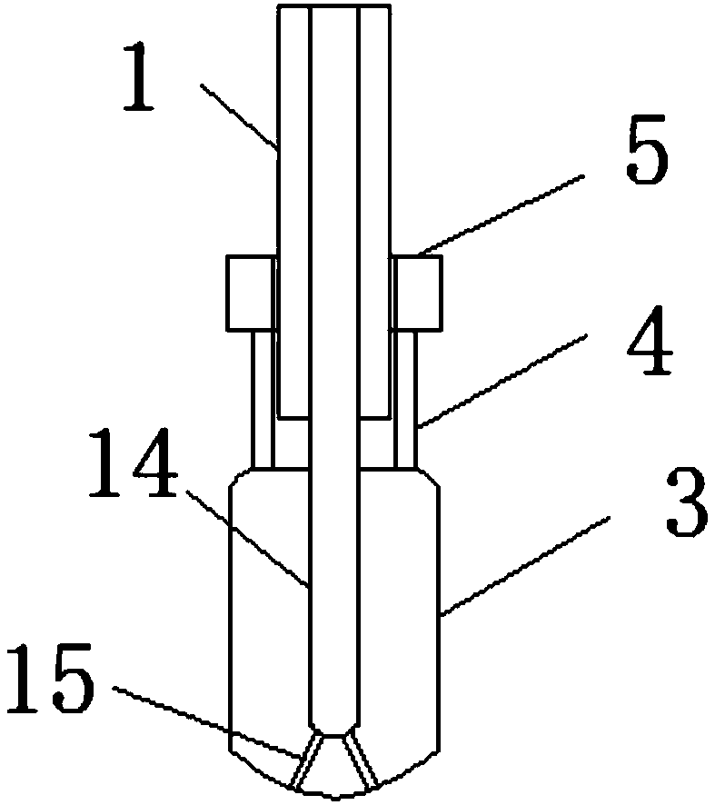
[0022] In addition, refer to Figure 1-Figure 3 , based on the above-mentioned embodiment, one end of the main shaft 1 is provided with threads, and the threads are matched with the connecting nut 5, so that the main shaft 1 is connected with the connecting nut 5, and the main body of the milling cutter can be freely replaced, and the chip guide groove 7 is arranged on both sides of the brush 8, The chip guide groove 7 is symmetrically distributed, so that the debris during the cutting and milling process of the device can be exported, and at the same time, the brush 8 removes the burrs, and one end of the rotating body 3 is fixedly connected with the drill bit 9, and a plurality of evenly distributed stoppers are set on the drill bit 9 10. Make the connection between the drill bit 9 and the rotating body 3 stable. Multiple distributed blocks 10 can connect multiple cutting blocks 11. Threaded holes are set on the blocks 10. The threaded holes match the fixing bolts 12, so that...
PUM
 Abstract
Description
Claims
Application Information