
Anti-blocking device of spiral squeezer

A screw press, anti-clogging technology, applied to presses, manufacturing tools, etc., can solve problems such as blockage of screw presses

Inactive Publication Date: 2017-10-24
邓韶光
View PDF0 Cites 2 Cited by
  • Summary
  • Abstract
  • Description
  • Claims
  • Application Information

AI Technical Summary

Problems solved by technology

[0008] In order to solve the existing clogging phenomenon of the screw press machine, the present invention proposes a solution, which consists of a rotating shaft welded, a U-shaped perforated plate, and a cover plate

Method used


Image

  • Anti-blocking device of spiral squeezer
  • Anti-blocking device of spiral squeezer
  • Anti-blocking device of spiral squeezer

Examples


Embodiment Construction

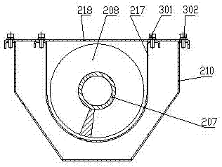
[0014] Figure 4 It is an axonometric view of the screw press anti-clogging device of the present invention, which is mainly composed of a rotating shaft welded, a U-shaped perforated plate 217, and a cover plate 218. For the convenience of observation and illustration, the cover plate 218 is hidden in the figure. The U-shaped perforated plate 217 is fixedly connected with the cover plate 218 by bolts 301 to form a U-shaped space. The rotating shaft is welded and installed in the U-shaped space and coincides with the half-circle axis of the U-shaped space. The deflector 210 is connected to the cover plate 218 by bolts 302 Fixed connection forms a closed space to prevent the leakage of odor in the closed space (see image 3 ).

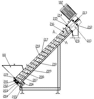
[0015] The rotary shaft welding of the present invention is based on the existing rotary shaft welding structure (the lower bearing shaft 206, the rotating shaft 207, the forward spiral blade 208, the reverse spiral blade 216, and the upper bearing sha...


PUM


Abstract

The invention discloses an anti-blocking device for a screw press, which is mainly composed of a rotating shaft welding, a U-shaped porous plate and a cover plate; the rotating shaft welding is composed of a lower bearing shaft, a rotating shaft, forward spiral blades, and reverse spiral blades , Stirring plate, and upper bearing shaft are welded, and the stirring plate is welded to the last pitch of the forward spiral blade and the first pitch of the reverse spiral blade; the U-shaped perforated plate and the cover plate are fastened by bolts to form a U-shaped space. The rotating shaft is welded and installed in the U-shaped space. When the rotating shaft is welded and rotates in a certain direction, the material will rise along the forward spiral blade, and at the same time, the reverse spiral blade will convey the material from the top to the downward direction, and the material will be squeezed in the end-to-end contact area between the forward spiral blade and the reverse spiral blade. During the extrusion process, the material will form a static accumulation block in the U-shaped space, and the agitation plate in the welding of the rotating shaft will stir the static material accumulation during the rotation movement to prevent the material accumulation from forming and growing. Phenomenon, to prevent the clogging of the screw press during the pressing process.

Description

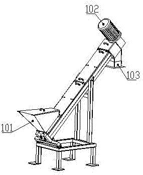
technical field [0001] The invention relates to a screw press machine, in particular to an anti-clogging device for a screw press machine. Background technique [0002] In terms of life and production, material pressing and conveying are widely used. The screw press has the characteristics of simple structure, low cost, reliable performance and low maintenance cost, and has dual functions of pressing and conveying. figure 1 It is an axonometric view of an existing screw press machine. The material enters from the feed hopper 101 and is driven by a geared motor 102 to be squeezed and dehydrated, and then delivered to the discharge port 103 for output. [0003] figure 2 It is a cross-sectional view of a screw press, the lower bearing shaft 206, the rotating shaft 207, the forward spiral blade 208, the reverse spiral blade 216, and the upper bearing shaft 214 are welded to form the rotating shaft, and the lower fixed plate 204 is connected to the lower perforated plate 217, g...

Claims


Application Information

Patent Timeline
Patent Type & Authority Applications(China)
IPC IPC(8): B30B9/14B30B15/00
CPCB30B9/14B30B15/00
Inventor 邓韶光
Owner 邓韶光
Learn More