Electrolyte cleaning device

A cleaning machine and electrolyte technology, applied in the field of electrolyte cleaning machines, can solve the problems of increasing the difficulty of crushing, and achieve the effects of increasing the fixing effect and improving the crushing effect.

Active Publication Date: 2017-10-24
HTC METALLURGICAL EQUIP CO LTD XINXIANG VIBRATION
View PDF9 Cites 10 Cited by
  • Summary
  • Abstract
  • Description
  • Claims
  • Application Information

AI Technical Summary

Problems solved by technology

If the anode guide rod set 1 is not properly fixed, it will increase the difficulty of crushing at the selected crushing point

Method used


Image

  • Electrolyte cleaning device
  • Electrolyte cleaning device
  • Electrolyte cleaning device

Examples


Embodiment Construction

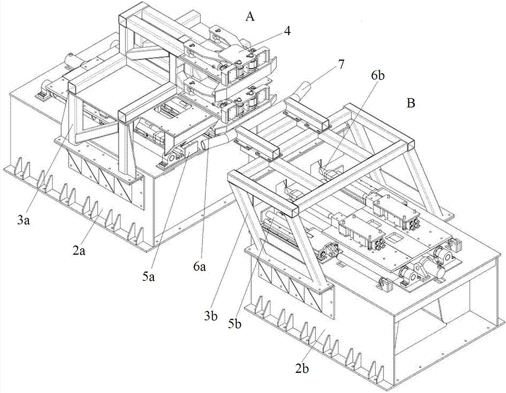
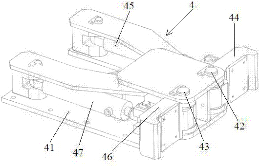
[0025] The concrete structure of a kind of electrolyte cleaning machine of the present invention is as follows: Figure 1~Figure 7 As shown, it includes a first cleaning part A and a second cleaning part B arranged at intervals along the left and right directions, the first cleaning part A includes a base 2a, a double-layer support 3a is fixed above the base 2a, and each layer of the double-layer support 3a is installed There is a guide rod clamping mechanism 4, and the upper end of the base 2a is equipped with a carbon block clamping mechanism 5a and a crushing mechanism 6a. Two guide rod clamping mechanisms 4 are arranged at intervals along the up and down direction. The second cleaning part B includes a base 2b, a bracket 3b is fixed above the base 2b, a carbon block clamping mechanism 5b and a crushing mechanism 6b are installed on the upper end of the base 2b, and a cable guide rod 7 is installed on the bracket 3b. The guide rod clamping mechanism and the carbon block cl...


PUM


Abstract

The invention relates to an electrolyte cleaning device. When the electrolyte cleaning device disclosed by the invention is used, two groups of guide rod clamping mechanisms which are arranged up and down at intervals are respectively clamped on different rod sections of an aluminum guide rod to preliminarily limit the motion of an anode guide rod group; and the displacement of carbon blocks is limited through a carbon block clamping mechanism. According to the electrolyte cleaning device disclosed by the invention, the anode guide rod group of higher level is sectionally fixed in an up-down direction, so that the improvement on a fixing effect is facilitated; further, after the anode guide rod group is preliminarily limited by the guide rod clamping mechanism, the carbon block clamping mechanism is driven to do a clamping action so that the carbon blocks can be accurately clamped and positioned by a clamping surface. Meanwhile, by adopting clamping claws of the guide rod clamping mechanism, an aluminum guide rod is clamped and fixed from a front side surface and a rear side surface of the aluminum guide rod; and the carbon blocks are clamped and fixed by the carbon block clamping mechanism from left sides and right sides of the carbon blocks. According to the application, the anode guide rod group can be accurately fixed on a set position, so that the improvement on a crushing effect is facilitated.

Description

technical field [0001] The invention relates to an electrolyte cleaning machine. Background technique [0002] When aluminum is produced by electrolysis, carbon is used as the anode, aluminum liquid is used as the cathode, and an electrochemical reaction is carried out under a suitable environment to obtain aluminum. The anode carbon block is placed into the electrolyte through the anode guide rod group. The structure of the anode guide rod group 1 is as follows figure 1 As shown, it includes an aluminum guide rod 11 and a steel claw 12 fixed on the lower end of the aluminum guide rod 11 . The steel claw 12 includes at least two steel columns 13, and the steel columns 13 are inserted into the anode carbon block and drive the anode carbon block to move. [0003] During the service life of the anode carbon block, as the anode carbon block is gradually consumed, the electrolyte produced during the electrolysis process will adhere to the surrounding of the residual electrode ...

Claims


Application Information

Patent Timeline
Patent Type & Authority Applications(China)
IPC IPC(8): C25C3/12
CPCC25C3/125
Inventor 韩瑞霞韩军林张继张全周凤飞
Owner HTC METALLURGICAL EQUIP CO LTD XINXIANG VIBRATION
Why Eureka
Try Eureka