
Electronic product and rotating shaft mechanism thereof

A technology of electronic products and hinges, which is applied in the direction of electrical equipment casings/cabinets/drawers, pivot connections, electrical components, etc., and can solve the problems of flexible screen damage and incompatibility with flexible screens, etc.

Active Publication Date: 2017-10-24
LENOVO (BEIJING) CO LTD
View PDF5 Cites 40 Cited by
  • Summary
  • Abstract
  • Description
  • Claims
  • Application Information

AI Technical Summary

Problems solved by technology

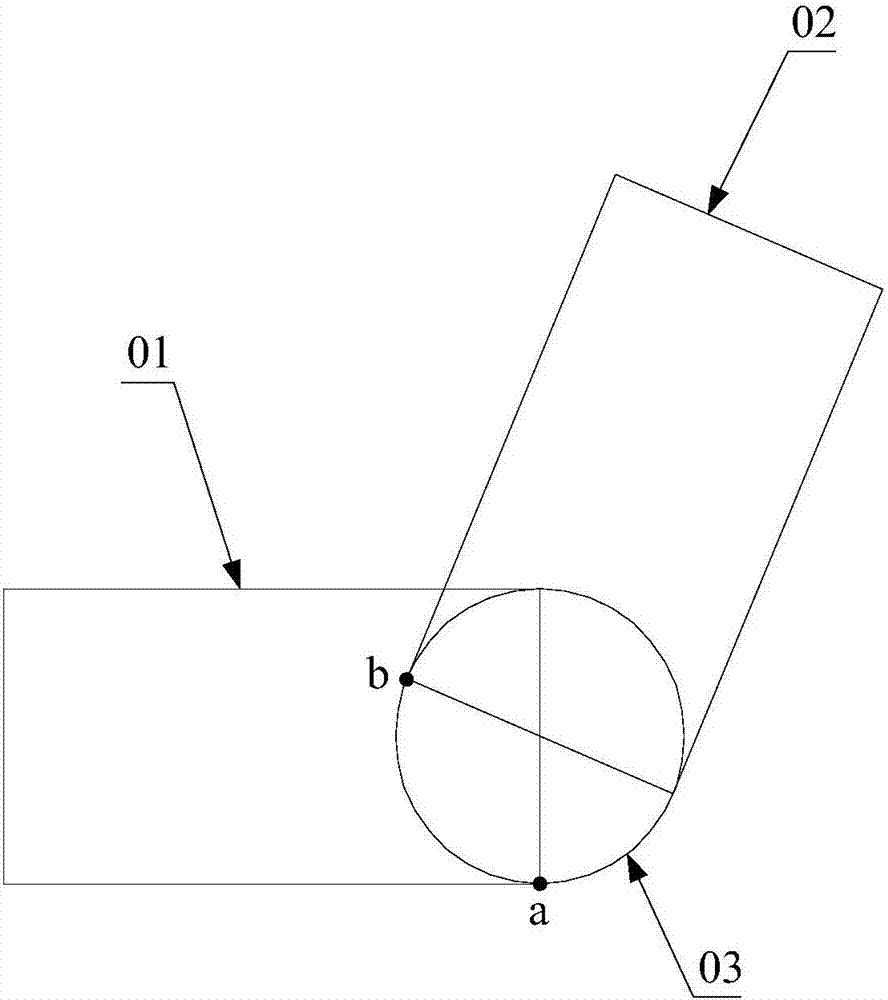
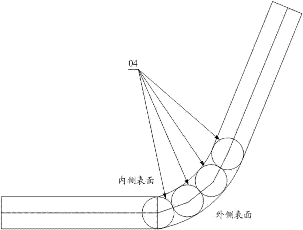
If the flexible screen is connected with these rotating shafts 04, when the flexible screen rotates to realize the closing of the electronic product (such as figure 2 As shown), the part of the flexible screen located on the inner surface of the rotating shaft 04 will be squeezed to bear the compressive force, and the part of the flexible screen located on the outer surface of the rotating shaft 04 will be stretched to bear the tensile force. When the electronic product is unfolded ( The expansion angle is greater than 180 degrees), the part of the flexible screen located on the inner surface of the rotating shaft 04 will bear the tensile force, and the part located on the outer surface will bear the compressive force, so no matter whether the electronic product is closed or unfolded, this kind of rotating shaft mechanism will affect the flexible screen. damage, so it is also not suitable for use with flexible screens

Method used


Image

  • Electronic product and rotating shaft mechanism thereof
  • Electronic product and rotating shaft mechanism thereof
  • Electronic product and rotating shaft mechanism thereof

Examples


Embodiment Construction

[0031] The invention provides a rotating shaft mechanism, which can be used in conjunction with a flexible screen, without applying compressive force or stretching force to the flexible screen and causing damage to the flexible screen.

[0032] The following will clearly and completely describe the technical solutions in the embodiments of the present invention with reference to the accompanying drawings in the embodiments of the present invention. Obviously, the described embodiments are only some, not all, embodiments of the present invention. Based on the embodiments of the present invention, all other embodiments obtained by persons of ordinary skill in the art without making creative efforts belong to the protection scope of the present invention.

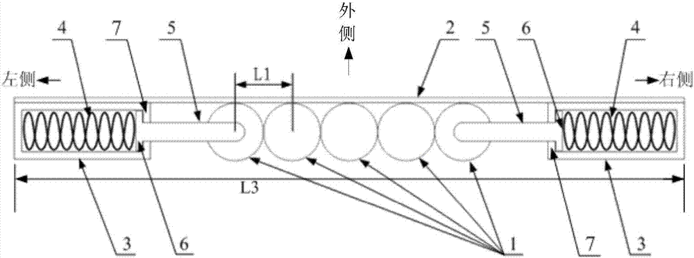
[0033] Such as image 3 with Figure 4 As shown, the main improvement of the rotating shaft mechanism provided by the embodiment of the present invention is that the sliding part 5 and the fixing part 3 are added on the basis...


PUM


Abstract

The invention discloses a rotating shaft mechanism which comprises a rotating shaft group, fixing parts and sliding parts, wherein the rotating shaft group comprises at least two parallelly arranged rotating shafts; the fixing parts are disposed on the two sides of the rotating shaft group; and the sliding parts are used for connecting the rotating shaft group with the fixing parts and at least disposed on one side of the rotating shaft group. When the rotating shafts at the symmetric positions are close to or far away from each other, due to the action of the sliding parts, the distance between the rotating shaft group and the fixing parts changes in the length direction of the rotating shaft mechanism. According to the rotating shaft mechanism, the sliding parts and the fixing parts are additionally arranged on the basis of an original rotating shaft mechanism. The sliding parts and the fixing parts can offset the displacement change generated by the movement of the rotating shafts being close to or far away from each other, it is guaranteed that the length of the outer side of the rotating shaft mechanism is unchanged, and a flexible screen laid on the rotating shaft group and the fixing parts is not stretched or compressed. Therefore, the rotating shaft mechanism can normally cooperate with the flexible screen for use, and the damage to the flexible screen is avoided. The invention also provides an electronic product with the rotating shaft mechanism.

Description

technical field [0001] The present invention relates to the technical field of electronic products, in particular to a rotating shaft mechanism, and also relates to an electronic product having the above rotating shaft mechanism. Background technique [0002] With the development of science and technology, users have higher and higher requirements for the use of electronic products, resulting in more and more diversified functions of electronic products, and many new forms of electronic products have emerged, such as mobile phones with flexible screens. [0003] A flexible screen refers to a display screen that can be bent, which can further optimize the performance of electronic products. At the same time, the flexible screen also has the property of being non-stretchable, that is, the flexible screen cannot withstand compression or stretching. It will cause damage to the flexible screen, so it is necessary to ensure that the components such as the rotating shaft mechanism ...

Claims


Application Information

Patent Timeline
IPC IPC(8): F16C11/04F16C11/12H05K5/02
CPCF16C11/04F16C11/12H05K5/0226G02F1/133305G06F1/1652G06F1/1681H05K5/0017H05K5/0217
Inventor 张然
Owner LENOVO (BEIJING) CO LTD
Learn More