Cam rope drive robotic fishtail swing device with shaft replacement door type mechanism

A technology of swing device and cam rope, which is applied to non-rotating propulsion elements and other directions, can solve the problems such as the difficulty in controlling the irregular speed change of the motor, increase power consumption and control difficulty, and achieve the solution of limited space at the end of the movement and limited load, control The effect of problem simplification

Inactive Publication Date: 2016-05-04
BEIHANG UNIV
View PDF7 Cites 14 Cited by
  • Summary
  • Abstract
  • Description
  • Claims
  • Application Information

AI Technical Summary

Problems solved by technology

[0004] In the traditional design of using independent steering gear or other types of motors (here we take the steering gear as an example) to provide power for the rope drive, the steering gear and the rope are all configured in one-to-one correspondence, which will increase the number of motors proportionally with the joints. Power Consumption and Difficulty of Control
On the other hand, for a robotic fish with a single motion law, that is, the specific joint rotation end of the robotic fish is a specific variable speed motion, which requires the motor speed to correspond to it, and it is difficult to control the irregular variable speed rotation of the motor.

Method used


Image

  • Cam rope drive robotic fishtail swing device with shaft replacement door type mechanism
  • Cam rope drive robotic fishtail swing device with shaft replacement door type mechanism
  • Cam rope drive robotic fishtail swing device with shaft replacement door type mechanism

Examples


Embodiment Construction

[0079] The present invention will be further described in detail below in conjunction with the accompanying drawings.

[0080] Rope Driven Robotic Fishtail Swing Device with Single Door and Single Cam

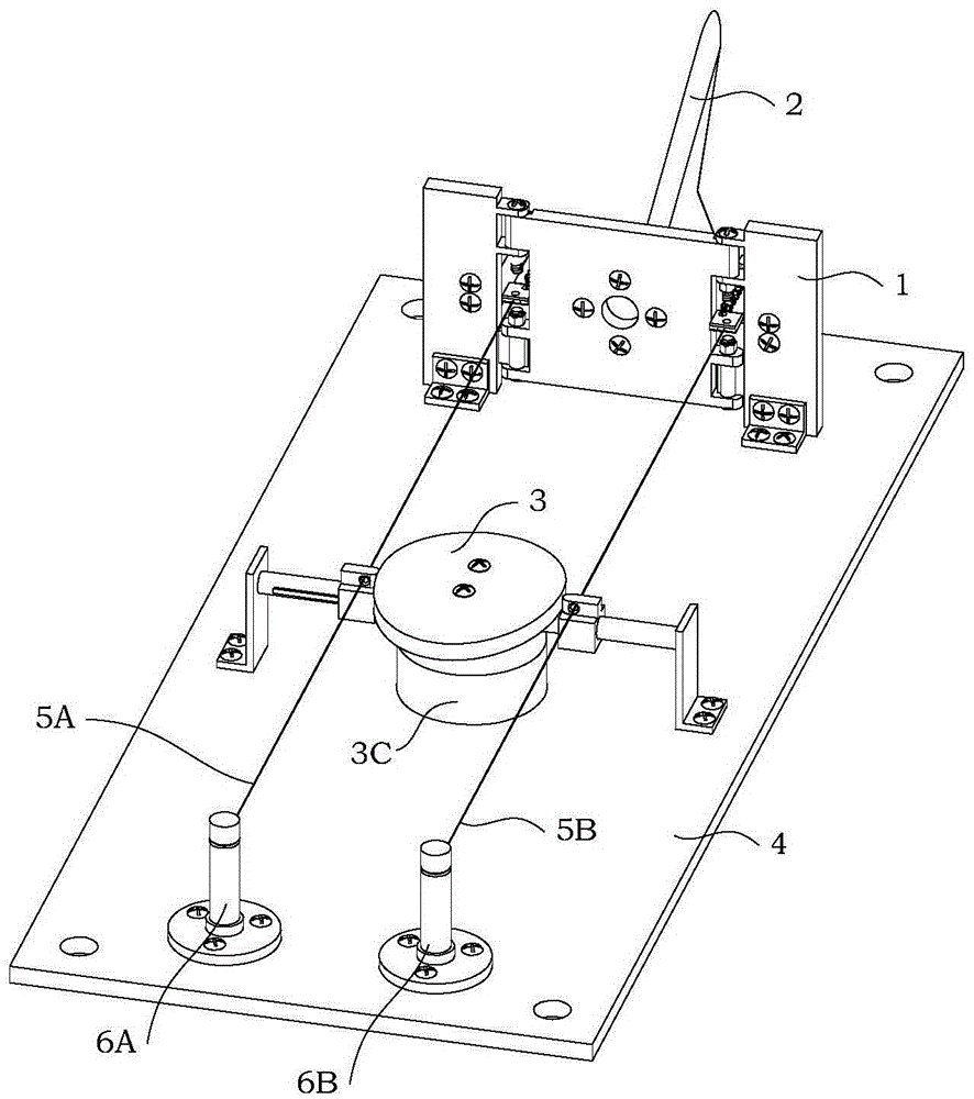
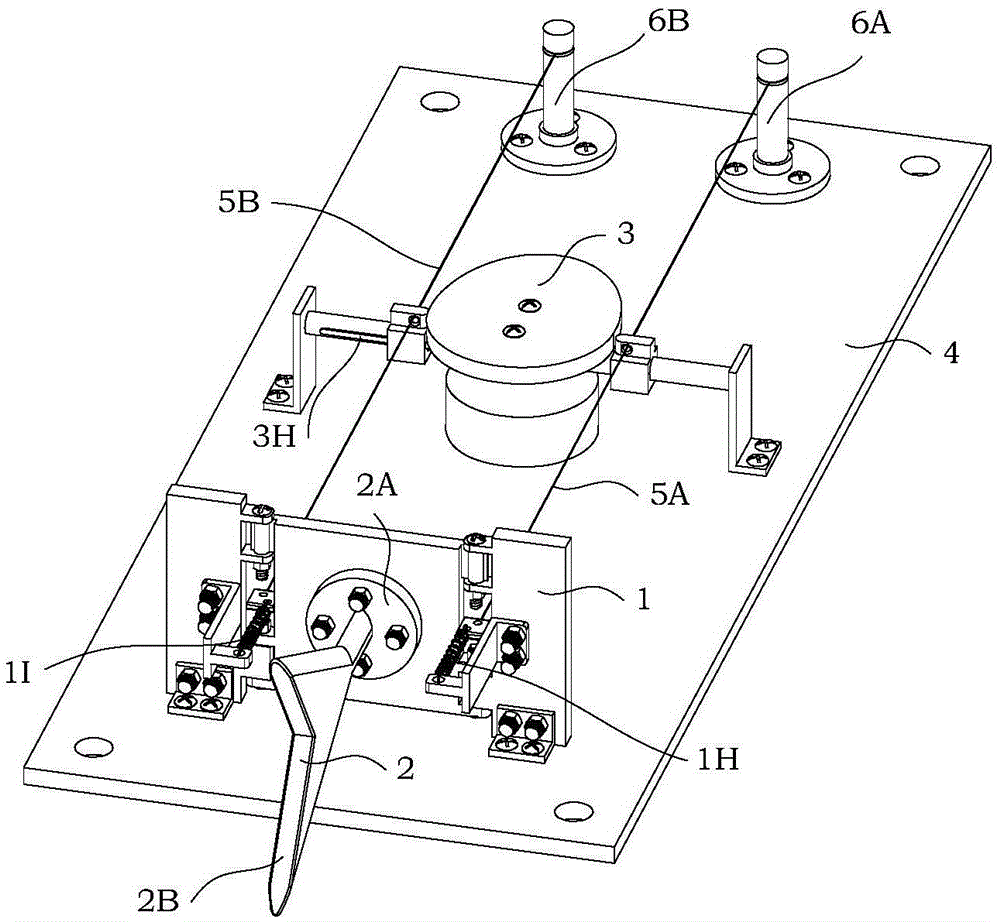
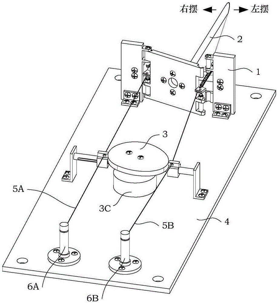
[0081] see figure 1 , Figure 1A , Figure 1B , Figure 1C , Figure 1D As shown, a kind of cam rope-driven machine fishtail swinging device (also can be called single-door single-cam rope-driven machine fishtail swinging device) with shaft-changing door-type mechanism designed by the present invention, the single-door single-cam rope The drive machine fishtail swinging device includes a replaceable shaft door mechanism 1, a machine fishtail 2, a disc cam drive mechanism 3, a base 4, A stay cord 5A, B stay cord 5B, A column 6A and B column 6B. The base 4 is provided with a mounting hole for mounting a limit. Such as the mounting holes for fixedly installing the A column 6A and the B column 6B. Such as the mounting holes for fixedly installing the A bracket 3I and the B b...


PUM


Abstract

The invention discloses a cam rope drive robotic fishtail swing device with a shaft replacement door type mechanism. The device comprises the shaft replacement door type mechanism, a door frame A, a door frame B, a disc-shaped cam drive mechanism, springs and pull ropes. The door frame A is installed on one side of the shaft replacement door type mechanism and the door frame B is installed on the other side of the shaft replacement door type mechanism. The springs and the pull ropes are installed on the two sides of a first door. Under the condition that a direct-current motor drives a disc-shaped cam to rotate, the profile of a flange of the disc-shaped cam makes contact with a sliding block B sleeved with the corresponding pull rope, meanwhile, the profile of a base circle of the disc-shaped cam does not make contact with a sliding block A sleeved with the corresponding pull rope, and therefore the first door swings in a reciprocating manner under the effect of a sliding bearing. By the adoption of the device, the variable structure of the disc-shaped cam is combined with the springs and the pull ropes, so that rotary shaft movement of the shaft replacement door type mechanism is achieved. By the adoption of the device, a complex robotic fish fin control problem is converted into a structure and appearance design problem of the disc-shaped cam, so that the complexity of a robotic fish control system is effectively reduced.

Description

technical field [0001] The invention relates to a tail swinging device of a robotic fish, more particularly, a cam rope driven robotic fish tail swinging device with a shaft-changing gate mechanism. Background technique [0002] Robot fish is an underwater unmanned vehicle that imitates the swimming mode of fish. It has the characteristics of small size, light weight, good concealment, strong maneuverability, and fast swimming speed. It has great potential in underwater exploration and modern national defense. Huge application prospects have become a research hotspot in the field of robotics. [0003] The propulsion modes of biological fish are mainly divided into two categories: "Body and / or Caudal Fin" mode (BCF) and "Median and / or Paired Fin" mode (Median and / or Paired Fin, MPF). Most fish in nature adopt the BCF mode, so at this stage, scholars at home and abroad have devoted a lot of energy to researching the realization method of the body and tail swing of the robot f...

Claims


Application Information

Patent Timeline
Patent Type & Authority Applications(China)
IPC IPC(8): B63H1/36
CPCB63H1/36
Inventor 王建华赵子健吴星明陈伟海黄超
Owner BEIHANG UNIV
Why Eureka
Try Eureka